XMEye DVR Detailed setup guide, This model DVR (Digital Video Recorder) is designed especially for CCTV system. It adopts high performance video processing chips and embedded Linux system. Meanwhile, it utilizes many most advanced technologies, such as standard H.264 with low bit rate, Dual stream, SATA interface, VGA/HDMI output, USB mouse supported, IE browser supported with full remote control, mobile view(by phones), etc., which ensure its powerful functions and high stability. Due to these distinctive characteristics, it is widely used in banks, telecommunication, transportation, factories, warehouse, and irrigation and so on.
COMPRESSION FOMAT
Standard H.264 compression with low bit rate and better image quality
LIVE SURVEILLANCE
RECORD MEDIA
BACKUP
RECORD & PLAYBACK
ALARM
PTZ CONTROL
SECURITY
NETWORK
IMPORTANT: Check the unit and all the accessories after you receive the DVR.
Please disconnect the power before you connect the DVR with other devices (cameras, USB mouse, etc.). Don’t hot plug in/out.
How to Install Hard Drive?
Step1: Unscrew and Open the top cover
Step2: Connect the power and data cables. Place the HDD onto the bottom case as below. Step3: Screw the HDD as below.
Note: For convenience, please connect the power and data cables firstly, and then screw to fix.
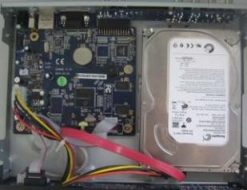
Connect the HDD Screw the HDD
XMEye DVR Detailed setup guide
Read More : XMEYE PC CMS Full Guide
Notice: The front panel descriptions are only for reference.

MODEL A:
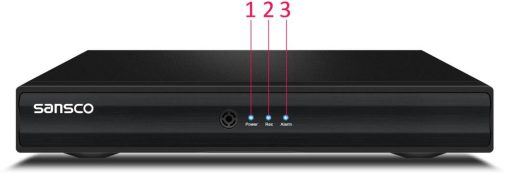
Up/Down/Left/Right/OK
MODEL B:
Notice: The rear panel descriptions are only for representation only. It is based on the rear panel of the 4-channel DVR.
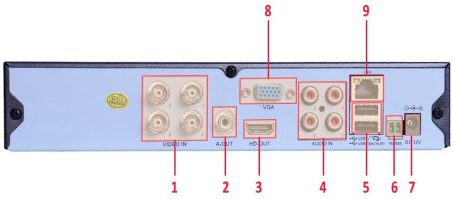
or update firmware; or connect to USB mouse
It uses two AAA size batteries.
Key points to check in case the remote doesn’t work.
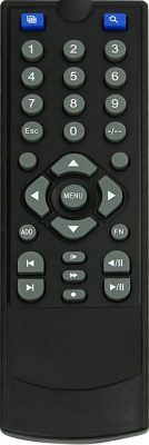
Single camera view/Multiple camera view.
Enter search (playback) mode
-/–, 0-9 Digital Buttons: The camera channel
MENU: DVR menu button. Also used as a confirm button.
ESC: Exit the current interface or status
Direction Buttons: Up/Down/Left/Right buttons
ADD: Remote Address. See below “Operation processes with remote controller to control multi-DVR” FN: Assist Function, i.e. PTZ Control, Color Setting. Choose any of them and press MENU to confirm. Enter playback mode interface
Previous Section. Next Section.
Slow Motion Replay. Fast Forward.
Record Mode. Use left/right direction buttons to go to desired channel, and use up/down button
to choose desired record mode. Press MENU to confirm and exit.
Operation processes with remote controller to control multi-DVR
The default device ID of the DVR is 0. It’s not necessary to reset the device ID when a remote is to be used to control a single DVR. However when controlling multiple DVRs with multiple remote controllers, you would need to configure the device ID, please refer to below steps:
Activate remote controller to control the DVR: Turn the IR sensor of the remote controller towards the IR receiver on the front panel, press the “ADD” button on the remote, then input device ID of the DVR to be controlled (Range from: 0-998; the default device ID is 000) and press MENU to confirm.
You can check the device ID of a DVR from Main Menu – System – General – DVR No. You can also set multiple DVRs with the same device ID however this can cause interference if the DVRs are kept close to each other.
It supports USB mouse through the ports on the rear panel.
NOTE: If mouse is not detected or doesn’t work, check below steps:
During live: Double-click on any camera window for the full screen mode. Double-click again to return to the previous screen mode. Right click to reveal the control menu on the screen.
In Configuration: Click to enter a particular option. Right click to cancel the option or to return to the previous menu.
In order to input a value in a particular screen, move cursor to the input box and click. An input window will appear. It supports digits, alphabets and symbols as inputs. Click or to input Capital letters and symbols;

You can change some values using the mouse wheel, such as time. Move cursor onto the value and roll the wheel to change value.
It supports mouse drag. For e.g. setting up motion detection area, click customized, hold down the left button and drag to set motion detection area.
In Playback: Click to choose the options. Right click to return to live mode.
In Backup: Click to choose the options. Right click to return to previous picture.
Note: Mouse is the default tool for all operations unless an exception, as indicated.
Before you power on the unit, please make sure all the connection is good.
Power on the DVR
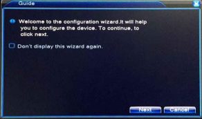
Step1: connect the DVR with the power socket via the power adapter. Step2: the device will be loaded, and the power indicator will display blue. Step3: before start, a wizard/guide dialogue box will pop-up and show some information about time zone and time setup, etc.
Note:
The wizard guide will take you to the settings on the
Time/Language/Network Test, just follow the on-screen instruction and click the Next Button. If you do not wish to get the pop-up dialogue box each time you turn on your DVR, you can also turn it off.
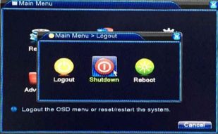
You can shut down the device by using the USB mouse.
Step1: Enter into Main Menu and select “Logout” – “Shut Down” icon. This will take you to a shutdown window.
Step2: Click Shutdown. Then the unit will power off after a while. Step3: Disconnect the power.
User can login or log off the DVR system.
The default user name is “admin”. There is no password, just leave it blank. For operational on changing password, adding or deleting users, please refer to section 4.5.2 Account.
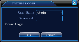
Note: If you forget the password, contact us immediately. We have super password for your DVR, you can email us with the following information and we will send you a unique password: Your model number, the date/time display on your screen. Password varies from date to date.
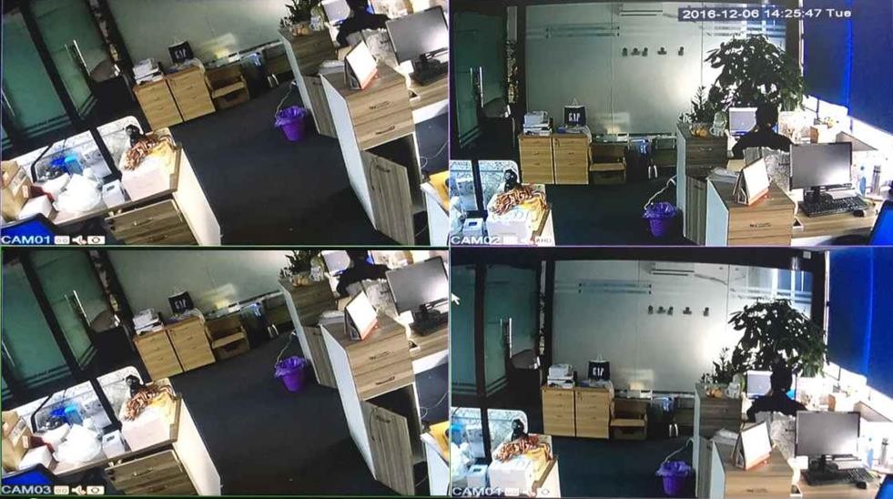
Understanding the meaning of the icons on preview mode. 2016-12-06 14:25:47 Tue: The current date/time CAM01: Camera Channel
: Camera is recording.
: Motion detection is ON.
: Video loss on camera channel
: Audio recording. Default camera does not support audio recording
AHD/TVI/CVI/Auto: The signal mode for the camera. Double click on this icon to change the signal mode.
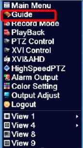
In the preview mode, right click your mouse to access the shortcut menu (on the right).
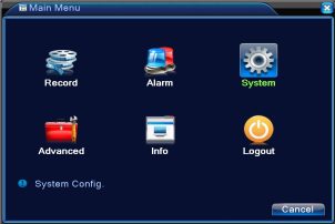
Choose Main Menu and log in, you should see this:
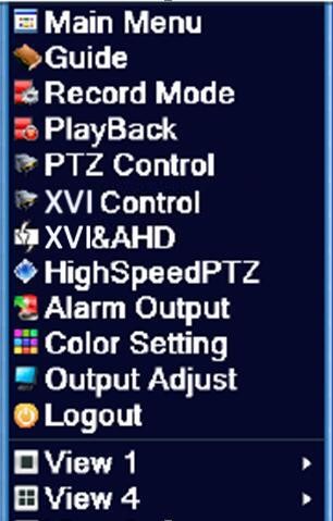
In preview mode, right-click and choose Guide.
The wizard guide will take you to the settings on the Time/Language/Network Test, just follow the on-screen instruction and click the Next Button. If you do not wish to get the pop-up dialogue box each time you turn on your DVR, you can also turn it off.
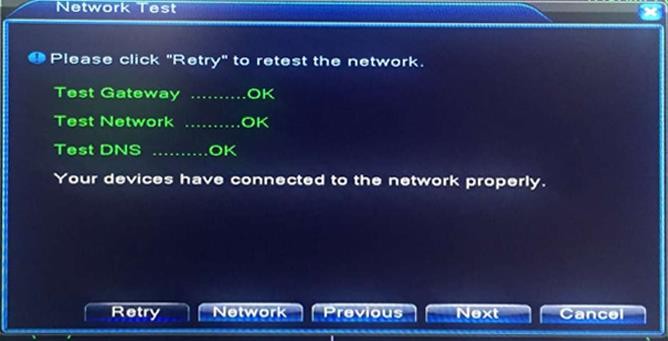
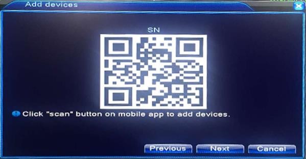
Clink Next to start the wizard setup guide, on the next dialogue box you will be able to configure the date and time for the DVR. Following the steps, you will be able to Enable/Disable the Summer Time, check the network status for the DVR, and download the APP: Xmeye. And use the Xmeye APP to scan the SN code of your DVR for remote access.
Note: For remote access, you can also refer to the Quick Setup Guide (the printed material) and follow the instruction which is simple and straightforward.
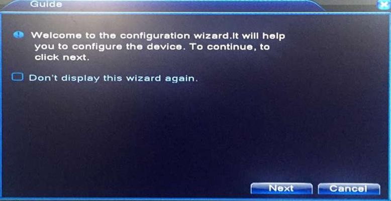
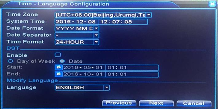
Check this box if you do not wish to get the wizard box each time you turn on the DVR. But it is recommended that you do not do so.
You can set the time zone, date and time, format, etc.
You can enable/disable the Summer Time. You can also set the Language here.
Network test: Make sure your DVR is connected with your router using a network cable. You should be able to see them showing as [OK] before you are able to remotely access the DVR. If you do not see the OK status for Gateway, Network, DNS, Click “Network”. And enable DHCP. And try again.
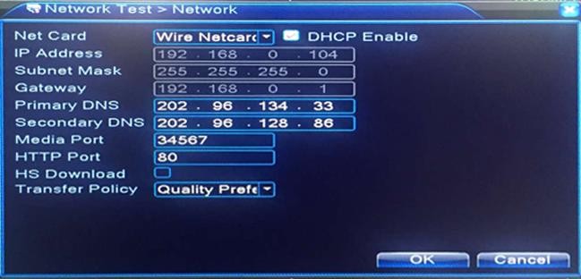

Enable DHCP, and click OK, go back to test the network again, till you see [OK] for Gateway/Network/DHCP.
The SN Code for the DVR. On your APP: Xmeye, scan the code below when you are remotely accessing the DVR.
The iOS APP: Xmeye
The Android APP: Xmeye
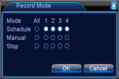
In Preview Mode, right click your mouse and choose Record Mode. You can also go to Record Mode from “Main Menu” – “Record” – “Record Config”, from there you will see more available setting options.
On the Ref. screen, “○” means unselected, “●” means selected. The screenshot (on the right side) shows all channels are set at Schedule Recording mode.
【Schedule】This allows you to set up flexible recording schedules for daily or weekly recording.
【Manual】Channel camera will record continuously after you set it at Manual.
【Stop】Channel camera will stop recording regardless of any actions.
To go to playback mode, Right click the mouse and choose Playback. You can also go from: “Main Menu” – “Record” – “Playback”.
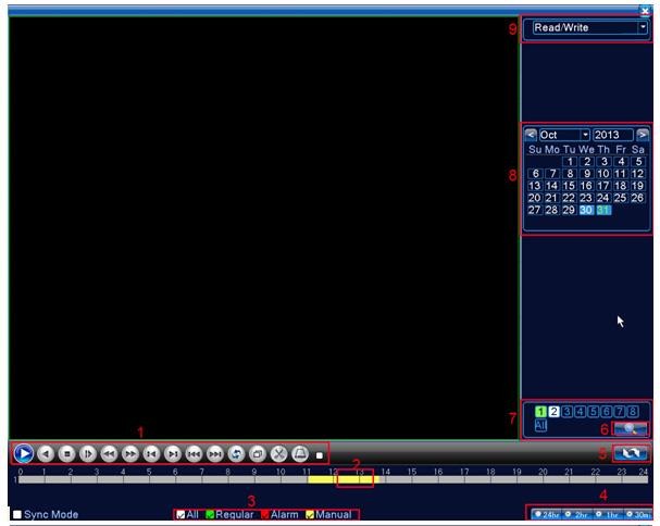

Explanation:
|
1 |
Playback Control |
2 |
Time Bar |
3 |
Recording Type |
4 |
Time Format |
|
5 |
Search Type (Date or Time) |
6 |
Search |
7 |
Channels |
8 |
Date |
|
9 |
Choose Your Storage |
10 |
Recorded File info. |
11 |
Recorded Files |
|
|
|
Icon |
Function |
Icon |
Function |
|
|
Play/Pause |
|
Play Backward |
|
|
Slow Playback |
|
Reverse Fast |
|
|
Fast forward |
|
Previous Frame |
|
|
Next Frame |
|
Previous Recorded File |
|
|
Next Recorded File |
|
Repeat Playback |
|
|
Full screen |
|
Edit |
|
|
Stop |
|
Backup |
Note:

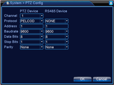
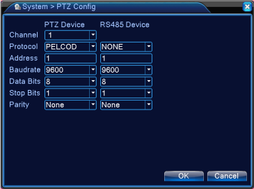
Settings for a PTZ camera must be configured before it is used. Before proceeding, verify that the PTZ camera and RS-485 of the DVR are connected properly.
To configure PTZ settings:
Note:
All setting parameters (baud rate, data bits, stop bits, parity, PTZ protocol and address) must be consistent with the PTZ camera connected.
The SANSCO DVR allows you to program presets, patrols, pattern, etc. for a connected PTZ camera.
Understanding PTZ Controls
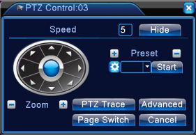
【Speed】Set the PTZ rotation speed/range.
【Zoom】Click /
button to zoom out/in..
【Hide】Hide the PTZ control menu.
【 Directional Pad 】 Support up to 8-directional control. Controls the movements and directions of the PTZ. The center button is also used to start the auto-scan of the PTZ.
【Preset】Presets can be set to move your PTZ camera to a desired preset location. Click Start to call the preset position.
【PTZ Trace】 Click to enlarge to full screen. Left-click and drag to adjust the camera angle. Left-click and hold and roll the wheel to zoom in/zoom out.
【Page Switch】Switch between menus.
Click Advanced,
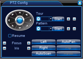
【Tour】 In Tour, you can move the PTZ to different key points and make it stay there for a defined duration before moving on to the next point. The key points are defined by presets. You will need to set all the preset positions before you use the Tour function.
【Pattern】The difference between Tour and Pattern is that you can add Focus/Zoom to key points in Pattern, but not in Tour.
【Focus】Used to adjust the focus of the PTZ.
【Iris】 Used to open up or close the iris of the PTZ.
【Auto Pan】The PTZ camera will pan horizontally.
【Left/Right】PTZ camera turns left or right.
【Auto Scan】Set up a serial of preset points (horizontal) and the camera will go from point to point (horizontally).
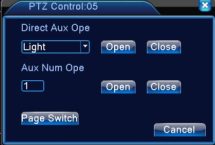 Click Page Switch,
【Direct Aux Operation】Light: Turns ON/OFF the PTZ light (if applicable).【Aux Number Operation】Turns ON/OFF the aux number per the Protocol.
In preview mode, right-click mouse and choose Coaxial Control. This function is NOT available for the SANSCO cameras.

In preview mode, right-click mouse and choose TVI & AHD.
The SANSCO DVR supports multiple signal types of the camera, i.e. AHD, Analog, CVI, TVI, IP Camera. If your camera channel does not display any image or display a black & white image on it, you may try to change the setting here. Normally the SANSCO DVR comes with AHD cameras, and we have set it at Auto mode, namely it will automatically detect and adjust the signal when it is connected to the DVR. So there is no need to change the setting, you probably need to change the signal types here only if you connect any non-SANSCO cameras to the DVR. However, contact us prior to any change on the settings.
In preview mode, right-click mouse and choose HighSpeedPTZ.
Left click your mouse to choose the desired channel camera, and right click to choose HighSpeedPTZ to enlarge the window to full screen, on the full screen you will be able to view the PTZ camera.
Note: This requires PTZ cameras. SANSCO camera does not have PTZ functions.
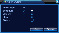
Alarm Output from: “Main Menu” – “Alarm” – “Alarm Output”.
On the Ref. screen, “○” means it is not in alarm status, “●” means it is in alarm status.
【Schedule】 This allows you to set up flexible alarm schedules on daily or weekly basis.
【Manual】 Channel camera will give alarm after you set it at Manual.
【Stop】Channel camera will stop giving alarm regardless of any actions.
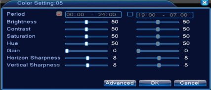
Note: The color setting is only available for Analog cameras, not for IP cameras.
In preview mode, right-click your mouse and choose Color Setting. On Color Setting, choose the desired channel camera and right-click to choose Color Setting. You can also schedule the colors at different times. You can also adjust the Brightness, Contrast, Saturation, Hue, Gain, Horizon Sharpness, and Vertical Sharpness.
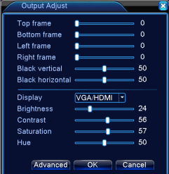 In preview mode, right-click your mouse and choose Output Adjust. Or you can access the Output Adjust from: Main Menu – Advanced – Output Adjust.
【Top Frame】The margins of the top.
【Bottom Frame】The margins of the bottom.
【Left Frame】The margins of the left side of the screen.
【Right Frame】The margins of the right side of the screen.
【Black Vertical】The black vertical section of the screen.
【Black Horizontal】The black horizontal section of the screen.
【Display: VGA/HDMI】Default.
【Contrast】Adjust the Contrast by dragging the white box on the line
【Saturation】Adjust the Saturation by dragging the white box on the line
【Hue】Adjust the Hue by dragging the white box on the line
【Advanced】Exit, Default
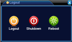 In preview mode, right-click your mouse and choose Logout. Or you can access the Log out from: Main Menu – Logout.
【Logout】Log out of the DVR. You will need password next time you log in the system.
【Shutdown】This is the safest way to turn off the DVR. If you do not need to use the DVR 24/7, or if the DVR is not in use for a long time, shut down the DVR and then disconnect the power adapter.
【reboot】The system will reboot itself and you will need password for the next login.
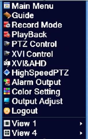
Depending on the DVR model (4-Channel / 8-Channel) you bought, you will have different options on the view mode. There is single-cam view, quad-cam view, multiple camera view, etc.
|
Main Menu |
Options |
Function |
|
Record |
Record Config. |
Configure the recording mode, i.e. schedule recording, motion detection recording, etc. |
|
Playback |
View playback on hard drive or USB backup storage. |
|
|
Backup |
Mange your backup storage that connects to the DVR. |
|
|
Alarm |
Motion Detection |
Set DVR to trigger alarm on certain channel(s) when movement is detected. |
|
Video Blind |
Set DVR to trigger alarm on certain channel(s) when any masking is detected. |
|
|
Video Loss |
Set DVR to trigger alarm on certain channel(s) when video loss is detected. |
|
|
Alarm Input |
The SANSCO DVR does not have Alarm Input channel hence this function is N/A. |
|
|
Alarm Output |
The SANSCO DVR does not have Alarm Output channel hence this function is N/A. |
|
|
Abnormality |
When an event (No detected HDD, HDD error, etc.) occurs on certain channel, the DVR will show error message, trigger a beep sound, or send an email. |
|
|
System |
General |
Time Zone, System Time, Date/Time Format, Language, Video Standard, Machine Name, Auto Logout, etc. |
|
Encode |
Compression, Video Resolution, Frame Rate, Bit Rate Type, Quality, Bit Rate, Frame Interval, etc. |
|
|
Network |
You can set basic network parameters here including: IP Address, Gateway, Port, DNS, etc. |
|
|
NetService |
PPPOE, NTP, Email, IP Filter, DDNS, etc. |
|
|
Display |
Channel Title, Time Display, Record/Alarm Status, Resolution, Region Cover, etc. |
|
|
PTZ Configuration |
Refer to PTZ Control In Section 3.5.5 |
|
|
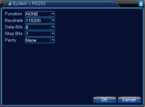
RS232 (N/A) |
You can set the Port Function/Baudrate/Data Bits/Stop Bits/Parity for the RS232 devices connected. |
|
|
Tour |
Set patrol mode and interval between key points |
|
|
Digital |
Set channel type, you can configure the setting here if you are connecting different cameras in to the SANSCO DVR, i.e. IP cameras + Analog cameras, etc. |
|
|
Storage |
Manage the hard drive or any storages connected to the DVR. You can set the hard drive at read/write, read only, and you can also format/partition the HDD from here. |
|
|
Advanced |
Account |
Manage all the users here, you can add/edit/delete users from here. |
|
|
Online User |
All the online users who are connected with the DVR. |
|
Output Adjust |
Refer to Section 3.5.11 |
|
|
Auto Maintain |
Schedule regular reboot, or automatic file deletion. |
|
|
Restore |
Reset all the personal settings and return them back to factory default. |
|
|
Upgrade |
Upgrade the firmware version of the DVR via a USB storage. |
|
|
Device Info |
Display the Device Information. |
|
|
Import/Export |
Export system logs or configuration to an external USB device (memory stick). OR import the configuration with an external USB device. |
|
|
HDD Info |
Display the hard drive connected to the DVR and its relevant information. |
|
|
Info |
BPS |
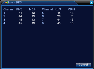
Display the Bit (per second) used for each channel camera. |
|
LOG |
Manage all the logs related to the DVR. |
|
|
Version |
Display DVR firmware, SerialNo (SN Code), NAT Status, etc |
|
|
Logout/Shutdown/ Reboot |
Refer to 3.5.12 Logout |
|
|
Logout |
|
|
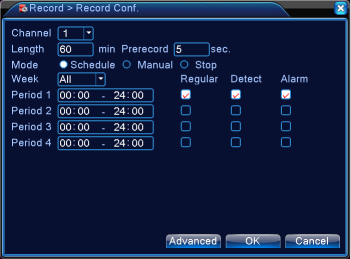
【Channel】Choose the channel camera to configure separately, or choose All to set all channel at the same time.
【Redundancy】If you check the box for “Redundancy”, the recording will be saved to both hard drives you installed, but make sure you have two hard drive installed inside the DVR, SANSCO 4/8-channel DVR supports maximum one hard drive only, so Redundancy is not available.
【Length】The length of each recording file, default 60min. This is not the total length of the recording.
【Pre-Record】Set the time in seconds to pre-record before the actual recording begins.
【Mode】Schedule, Manual or Stop. Refer to Section 3.5.3 Record Mode
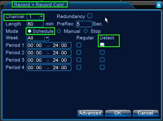
【Period】This is available only when you choose Schedule Record. You can manage up to 4 different periods within a day.
【Record Type】Regular, Detection or Alarm. The Record Type is only available when you choose Schedule Record. Regular: The camera will record based on the time schedule you set on the left side next to it. File type: R
Detect: The camera will record only when it detects movements, video-loss, or video masking. File Type: D
Alarm: The camera will record only when the DVR receives signals from “Alarm Input”, provided that the camera is set to record under “Alarm Input” setting. File Type: A. However, since there are no Alarm Input/Alarm Output on SANSCO DVR, this function is not available.
Note: You should be able to see the File Type when you are doing a Backup.
【Advanced】 Click Advanced to drop down the menu, it gives you the shortcut to go to Live View, copy the current settings, paste the copied settings to current page, set default, and go to Storage (Main Menu – Advanced – Storage).
Please refer to Section 3.5.4 Playback.
Recorded files can be backed up to various devices, such as USB flash drives, USB hard drives, or a DVD writer.
Note: The storage must be properly installed before the file backup. Do not try to stop the backup when it is in progress.


【Detect】Search the Storage that has been connected to the DVR. Try a few more times on this button.
【Backup】Once the DVR detects the Storage that connects to it, you can back up the file from your hard drive to the USB Storage. You can click “Backup”, on the next dialogue box you will see the Backup dialogue box.
You will be able to search the desired recorded files that you want to backup, you can search the files by: Type, Channel, and Time. Type: This drop-down menu allows you to choose files from Alarm Recording, Motion Detection Recording, Manual Recording, or General, etc. By default, it is set at ALL.
[Channel]: Choose the recorded files from desired channel camera. Choose ALL for all channels. [Start Time/End Time]: Set the start time and end time to search the desired recorded files. [Add]: Click Add to display the list of the search result.
[Remove]: Click Remove to remove the list of the search result.
[Backup Format]: Choose the file format for the backup files. Available options: H.264, AVI. [Start/Stop/Cancel]: To start the backup, stop the backup, or cancel the backup.
Note:
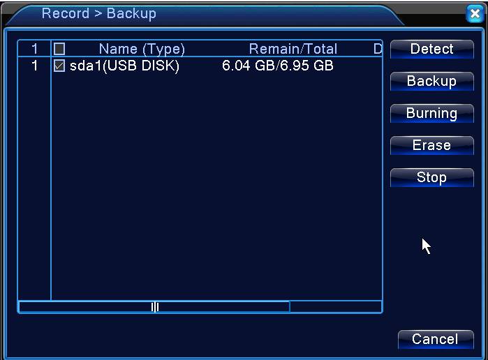
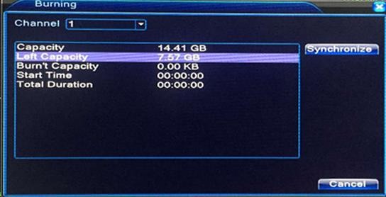
【Burning】Click Burning to enter the Burning option, you can choose the desired channel and synchronize the recording files to the extra Storage you installed to the DVR. Click Cancel to
Note:
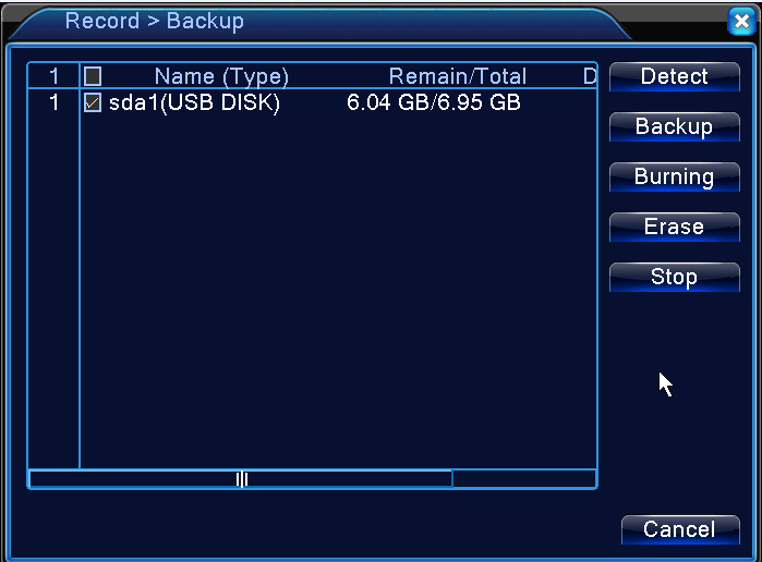
Erase files from a re-writable CD or DVD
Stop the Backup
Cancel and Exit
Under Alarm Menu, there is: Motion Detection, Video Blind, Video Loss, Alarm Input, Alarm Output, Abnormality
Note: SANSCO DVR does not support most of the Alarm functions because it does not have any Alarm Input/Output.
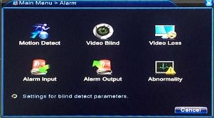
When the channel camera detect any movements, the DVR will trigger the motion detection alarm.
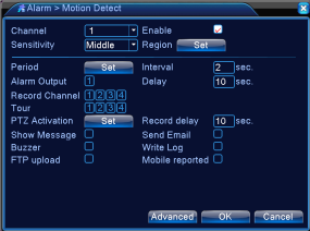
【Channel】Choose the channel camera to detect movements.
【Enable】Turn on or turn off the motion detection alarm.
【Sensitivity】Choose the sensitivity of the motion detection, from Lowest to Highest.
【Region】Click [set] to set up the motion detection masking. On the next screen, left click and mouse and drag to unselect the area, the pink area showed below will be monitored by the camera. Once there are movements in the pink area, the camera will send the signal to the DVR and further trigger the alarm, on the other hand, any movements fall within the white area below will NOT be monitored and detected.
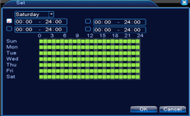
【Period】Schedule the timing for the motion detection activities. You can manage up to 4 different periods within a day. Click the time box to choose the Hour/Minute and it will reflect the same on the green table below:
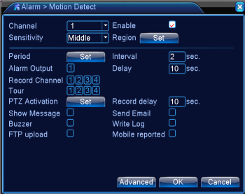 【Interval】Only one alarm will be triggered within the set interval regardless of how many movements.
【Alarm Output】Once movement is detected, the external alarm device connected to the DVR (via Alarm Output) will be triggered.
【Out Delay】The external alarm normally goes off after a while, however, if you set the Out Delay, then it will not go off immediately, instead it will go off after the set value (from 0 to 300s)
【Record Channel】Choose the channel(s) to record when an alarm is triggered. If you also check the box for FTP upload (below): the recording will be uploaded to FTP Sever as well.
【Tour】 Choose the channel(s) to patrol when an alarm is trigger. You can set the patrol interval (from point to point) via [Main Menu] – [System] – [Tour].
 【PTZ Activation】Set the PTZ Activation when the alarm is triggered. You can select any channel or multi channels. Make sure the channel is connected with a PTZ camera already because the SANSCO camera is not PTZ type. When an alarm occurs, the selected PTZ channel will rotate to the preset point, patrol, or zoom in/out, depending on your settings. Check the PTZ Activation menu (on the left):
You will be able to set the PTZ camera to rotate to preset point, Patrol from point to point, or Patrol from point to point plus zoom in/out. You can set differently for each channel if you like.
NOTE: Before you set up the PTZ Activation, you will need to configure the PTZ Control first, please refer to Section 3.5.5 PTZ control. To go to PTZ Control, please right click on the preview mode and choose PTZ control.
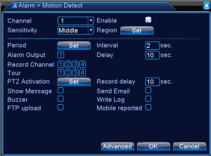
【Record Delay】When the alarm is off, the alarm recording normally stops, however, if you set the Delay, the alarm recording will not stop immediately after the alarm is off, instead, it will last a few more seconds/minutes, from 10-300s.
【Show Message】When an alarm occurs, a pop-up message will show up on the screen of the channel.
【Send EMAIL】When the channel camera detects movement, or an alarm occurs, the DVR will send an email as well. To configure the email settings, go to [Main Menu] – [System] – [NetService] – [Email].
【FTP upload】When an alarm occurs, the DVR will upload the recording file to FTP server, provided you have set up the record channel stated above. To configure the FTP Settings, please go to [Main Menu] – [System] – [NetService] – [FTP].
【Buzzer】If you check the box for buzzer, you will hear a beep sound when an alarm occurs.
【Write Log】If you check this box, the DVR will write the alarm information to the hard drive when an alarm occurs.
【Mobile Reported】If you check this box, you will receive a mobile notification when an alarm occurs.
【Advanced】Click Advanced, the drop-down menu gives you the shortcut to go to Preview Mode, copy the current settings, paste the copied settings to current page, reset to default, or go to Record Config (Main Menu – Record – Record Config.).
(Please refer to 4.3.1 Motion Detect because the settings and options are similar)
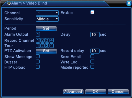 Whenever there is any masking on the channel camera, the DVR will trigger the video blind alarm, i.e. when the ambient lighting is too low, or if someone deliberately cover the camera lens result in video masking.
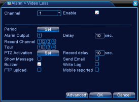
Whenever there is video loss on the channel camera, the DVR will trigger the video loss alarm, i.e. when the video cable is disconnected, this will result in video loss and further trigger the alarm.
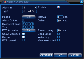
When the DVR receive any signals from the Alarm Input (extra alarm input device required), it will trigger the alarm. You will need to choose Normal Open so the DVR will automatically trigger the alarm when it receives the signals from Alarm Input Devices.
When the DVR detects any error or abnormal situation, i.e. storage error, IP confliction, disconnection, etc., it will trigger the alarm.
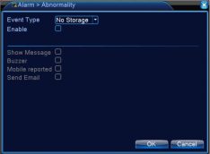
【Event Type】No Storage, Storage Device Error, Storage No Space, Net Disconnection, IP Conflict.
【Enable】Check the box to enable the alarm function.
【Show Message】When an error occurs (listed in Event Type), a pop-up message will show up on the screen of the channel.
【Buzzer】If you check the box for buzzer, you will hear a beep sound when an error occurs.
【Mobile Reported】If you check this box, you will receive a mobile notification when an error occurs.
【Send EMAIL】When an error occurs, the DVR will send an email as well. To configure the email settings, go to [Main Menu] – [System] – [NetService] – [Email].
Under System Menu, there is: General, Encode, Network, NetService, Display, PTZ Config., RS232/RS485, Tour, Digital
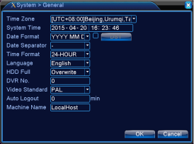 General
【Time Zone】Time zone that you want the DVR to use.
【System Time】The date and time for the DVR.
【Date Format】Choose the date format.
【Date Separator】Choose among: “.” and “-” and “/”.
【Time Format】Choose time format: 24-hour or 12-hour.
【Language】Support multiple language.
【HDD Full】Stop record: Stop recording when the hard drive is full. Overwrite: Overwrite the oldest recorded files and continue recording when the hard drive is full.
【DVR No.】Refer to 2.4 Control with Remote – Operation processes with remote controller to control multi-DVR.
【Video Standard】PAL or NTSC. PAL for Europe, NTSC for America.
【Auto Logout】Set the DVR to automatically logout after some time.
【Machine Name】Name your DVR.
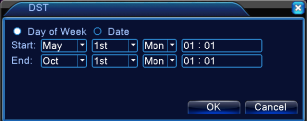
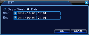 【DST】Check the box for DST (Summer Time) and click DST to see the dialogue box below. Setup per your preference.

Main Stream Setting
Sub Stream Setting: this is for use only in worse network conditions or when you remotely access the cameras via mobiles, to save bandwidth.
【Channel】Choose the channel camera.
【Compression】Standard H.264.
【Resolution】Resolution 1080N/960H/D1.
【Frame Rate】Adjustable from 5 to 25FPS
【Bit Rate Type】You can choose between VBR (variable bitrate) and CBR (constant bitrate). Under VBR, you can choose different Quality (up to 6, from lowest to highest). Under CBR, you can set different Bit Rate (Kb/s).
【Bit Rate】The higher the value, the better the video quality. Below is the bit rates normally used in different cases: 1080P (1024~8192kbsp), 720P (1024~4096kbps), 960H (869~4096kbps), D1 (512~2560kbps), HD1 (384~2048kbps), CIF (64~1024kbps), QCIF (64~512kbps).
【Frame Interval】Choose among 2~12s.
【Video/Audio】Choose whether to stream video or audio (SANSCO camera does not support audio streaming).
【Extra stream】Normally used when the network condition is not good or when you use mobile devices to remotely access the DVR.
Note:
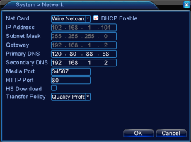 Network
【Net Card】The SANSCO DVR is installed with a wired Ethernet card, so by default it is a Wire Netcard as seen above.
【DHCP Enable】It is recommended that you check this box, and the DVR will automatically obtain an IP address from your router, if you have connect the DVR with your router using a network cable.
【IP address】When the box for DHCP Enable is uncheck, you can set the IP address of the DVR.
【Subnet mask】Set the subnet mask for the DVR. Default: 255.255.255.0.
【Gateway】Set the gateway for the DVR. Default: 192.168.1.1.
【Primary DNS】【Secondary DNS】Set the DNS for the DVR.
【Media port】The port used for the software client CMS. Default: 34567.
【HTTP port】The port used for webpage access. Default: 80.
【HS Download】High Speed download.
【Transfer Policy】Adaptive/Quality Preferred/Fluency Preferred. Choose any of the three per your preference. Adaptive means the DVR will automatically adjust the video quality and fluency, Quality Preferred means the DVR always prioritize the quality over fluency, and Fluency Preferred means the DVR will put fluency as priority over quality.
Choose the network service option and click the set button to configure the advanced network functions or double click the service button to configure the parameters.
Note: Unless otherwise specified, it is always recommended not to change the default setting under the NetService, because the default factory settings suit most cases. If you have any doubts or concerns, please contact us immediately before you make the change. You can also refer to another instruction DVR Network Setup Guide provided by us.
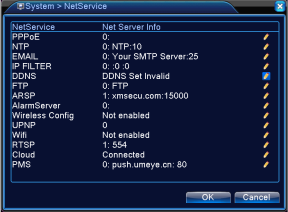
【PPPoE】User can directly connect the DVR to internet via ADSL, then input the user name and password;
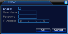
Check the box for Enable to enable the PPPoE setup.
Enter the username and password provided by your ISP (Internet service provider). Save the settings, and then reboot the device, if the PPPoE connection is successful, you will find the IP address for the DVR as showed in section 4.4.3 Network. You can further use the IP address on the client software CMS. The IP address will probably change from time to time because of the PPPoE connection. That’s why we recommend you to always use DHCP instead (refer to 4.4.3 Network).
【NTP】Network Time Protocol. User can synchronize the time zone for the DVR using the NTP setup.
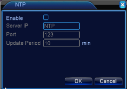 Note: * In order to use this function, you need to install the NTP server in your PC.
* Do NOT use this if you do not have a known NTP Sever. Check the box for Enable to enable the NTP setup.
Host Sever IP: Enter the IP address for the PC that you installed the NTP server. Port: Default: 123. You can change the port based on the real IP address of the PC that installed the NTP server.
Time Zone: Examples (London GMT+0, American Central Time GMT-6).
Update Period: The time interval for the DVR to refresh the time zone based on the setting. Default: 10 minutes.
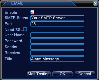
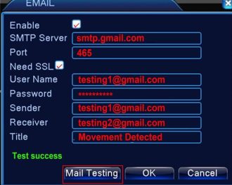 【EMAIL】If you have checked the box for [Send Email] in section 4.3.1 Motion Detect, you will receive an email when movement is detected. Check the box for Enable below to turn on the email alerts.
[SMTP Server]: For example, smtp.gmail.com
[Port]: Email server port number. For Gmail, you can use 465
[SSL]: Secure Sockets Layer (SSL) authentication protocol. If you use Gmail, check the box near “Need SSL” [User Name]: Enter the username for your Gmail. i.e. testing1@gmail.com.
[Password]: Enter the password for your Gmail account. [Sender]: Set the sender’s email address.
[Receiver]: Set the receiver’s email address. i.e., testing2@gmail.com. You can set up to 3 receivers. [Title]: Set the email title/subject.
When you finish, click Mail Testing, and if the setup is correct, you will see the message “Test Success”.
Note: If you come across any issues related to the email setup, please contact us immediately via email, we will reply in 24 hours with a solution. Failures on email setup do not necessarily due to the machine itself, sometimes it could just be the settings, or email server, etc.
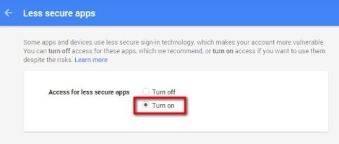
For Google Gmail, click the following link to configure the Gmail: http://www.google.com/settings/security/lesssecureapps
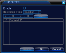
【IP Filter】User can set up both the IP whitelist and IP blacklist to manage the DVR access. If you set up the IP whitelist, only the users on the whitelist can access the DVR. If you set up the blacklist, the users on the blacklist won’t be able to access the DVR.
If the same IP address is on both the whitelist and blacklist, that IP address still won’t be able to access the DVR because the setting of blacklist overrides. You can manage up to 64 IP address for both whitelist and blacklist. Check the box next to Enable to set up the IP Filter function.
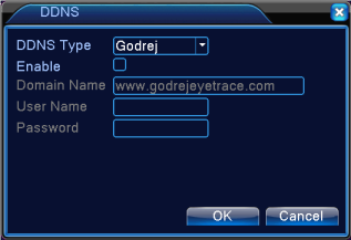
【DDNS】User can set up the DDNS and remotely access the DVR via DDNS on browsers.
Check the box next to Enable to set up the DDNS. Choose the DDNS Type, enter the domain name, username and password.
Note:
successful apply, user can access the server from the IE client by inputting that domain name.
How to access the DVR via DDNS or external IP address? (Take www.no-ip.com for example)
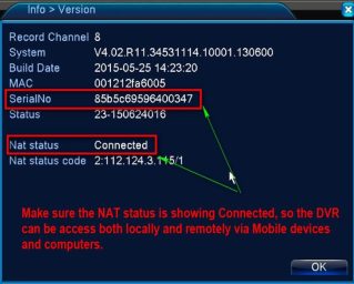
Step 1: Please connect your DVR to the router using a network cable, enable the DHCP option (4.4.3 Network), and make sure the DVR connects to the router and Internet successfully. See below:
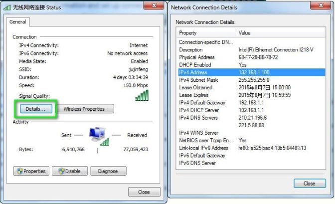
Step 2: Fix the DVR’s IP address
Use a computer which is connected to the same router and check the computer’s network information as below:
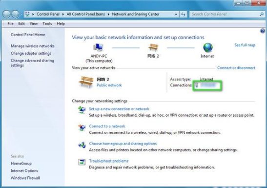
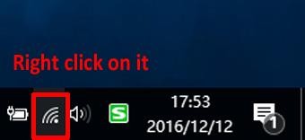
Right click on the Wi-Fi icon and choose Open Network and Sharing Center
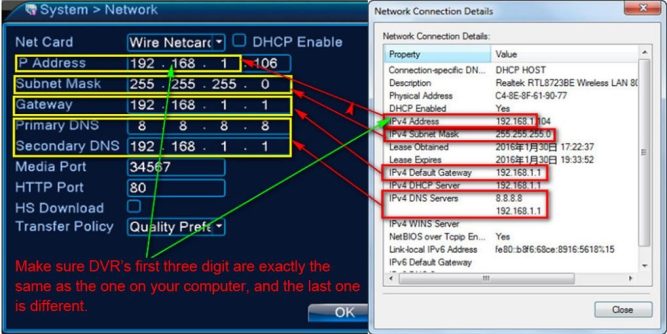
Step 3: Register a DDNS account. Here we take no-ip DDNS as an example. We go to www.no-ip.com.
Notice: if your network’s external IP is static, not dynamic, you don’t need to set up DDNS, you can skip step 3.
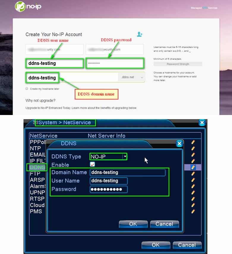
Register a DDNS Account
After you register an account, fill in the information of the DVR.
Step 4: On your computer, go to the router’s configuration page to do the port forwarding for the DVR’s IP address, http port and media port. Before you do this, check the DVR’s IP address, http port and media port per the screen below:
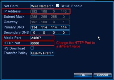
Click open this link for more information on the port forwarding before you configure: https://portforward.com/router.htm
Port forwarding example:
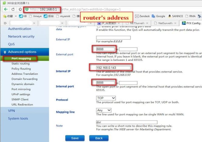
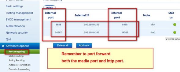
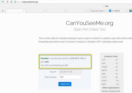
After you finish the port forwarding, you can click open this link www.canyouseeme.org to check whether the port is open.
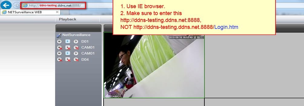
Use IE, you can skip the word “Login.htm” in the address bar, if you enter the wrong address with the words “Login.htm”, you may not be able to access the live video.
Finally, if the DDNS & port forwarding have been set up correctly, you can open this link: http://ddns-testing.ddns.net:8888 anywhere (with network access) to visit the DVR.
Mobile APP vs. Port Forwarding: If your remote access to the DVR will be using phone or tablet only, you may use the APP to access the DVR, which is simple to set up. If you use APP, setting up port forwarding and dynamic DNS is not necessary. If using a PC or Mac to access the DVR from a remote location, or if changing DVR settings remotely, setting up port forwarding is recommended. However, you may still use the webpage for remote login via www.xmeye.net on your PC or Mac, in this case, the port forwarding is still not necessary. For some people, the port forwarding is complicated and less people tend to use this function anymore.
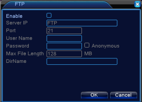
【FTP】
FTP is only available when an alarm occurs (refer to section 4.3.1 Motion Detect), in this case, it will upload the related recorded files to your FTP server.
[Enable]: Click Enable to set up the FTP upload. [Server IP]: IP address of the FTP server.
[Port]: Domain Port of the FTP server. Default 21.
[User Name]: Username for the FTP server login. [Password]: Password for the FTP server login.
[Anonymous]: Check this box for Anonymous login, no need to enter username/password. [Max File Length]: Maximum file size allowed to upload.
[DirName]: Set up the FTP path for the uploaded file.
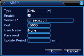
【ARSP】On occasion the DVR’s external IP may change because of the internet service provider. The ARSP option allows for remote browser login to the DVR to check for the DVR’s current external address even if it changes. This would allow you to remotely look up the DVR’s current IP, and manually update it in the app settings. This can be useful if you choose not to use dynamic DNS.
ARSP Setup Example:
Step 1: Go to System > Netservice > ARSP. Check “Enable”. Server IP is xmsecu.com Port, username, and password are default values and do not need to be modified. Click “OK”, “OK”, and then close.
Step 2: Go to Info > Version Write down the MAC number.

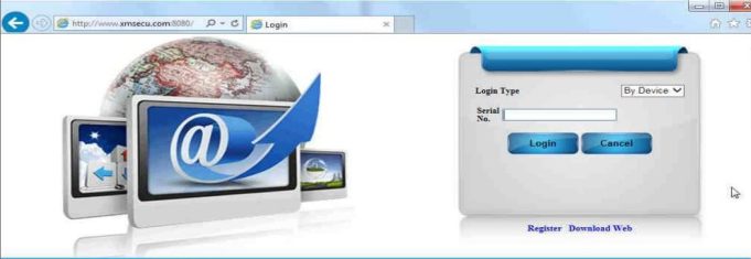
Step 3: Using a web browser, go to http://xmsecu.com:8080 and login using the MAC number. If it fails to login, verify the MAC number, and try logging in again. Current information about the DVR will be shown. “True IP” is the current external IP address of the DVR.
【Alarm Server】
When an alarm occurs, the DVR will upload the alarm information to the Alarm Server.
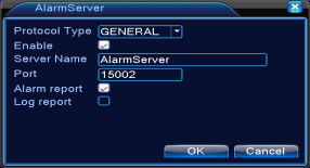
[Protocol Type]: GENERAL.
[Enable]: Check the box to enable the setup. [Server IP]: The IP address of the Alarm Server. [Port]: The port number of the device.
[Alarm Report] [Log Report]: Check the boxes to upload the alarm information/logs to server when an alarm occurs.
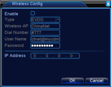 【Wireless Config】SANSCO DVR does not support this function. This allows the DVR to connect with the internet via 3G dial wireless Config.
[Enable]: Check the box to enable the wireless configuration. [Type]: Available from – WCDMD/TD-SCDMA/CDMA1.x/GPRS/EVDO [Wireless AP] 3G Wireless Access Point
[Dial Number]: 3G Dial Number [User Name]: 3G Username [Password]: 3G password.
[IP Address]: The IP address for the DVR after the successful 3G dial connection. Note: SANSCO DVR does not support this function.
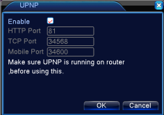 【UPNP】The UPNP protocol ensures the automatic port forwarding on your router.
[Enable]: Check the box to enable the setup. If you enable this setup, the router will automatically assign different port numbers to the DVR, when it is accessed by users via different methods.
[HTTP]: This is the port for use when you access the DVR using IE browsers.
[TCP]: This is the port for use when you access the DVR using the CMS software client. [Mobile Port]: This is the port for use when you access the DVR via mobile devices.
Note: In order to use this function, make sure the UPNP has been enabled on your router.
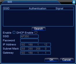 【Wi-Fi】User can connect the DVR with a Wireless USB Ethernet Card to get the DVR to work wirelessly with your router. Once you have connected USB Ethernet Card correctly, click Search to connect the DVR with your router.
Note:
【RTSP】To enable the RTSP port number for the DVR when you access the DVR from different browsers (Safari, Firefox, Chrome) or VLC player.

[Enable]: Check the box to enable the RTSP port number. [Port]: The default port number is 554.
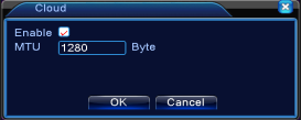
【Cloud】This shows whether or not the DVR has been connected with the network. You should read “Connected” when the DVR is already connected with the router. Double click Cloud to go to this screen. Make sure the Cloud is Enabled.
【Mobile Reported】Double click to enable the mobile report function. Check section 4.3.6 Abnormality – [Mobile Reported].
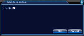
Note: SANSCO does not support the mobile report function.
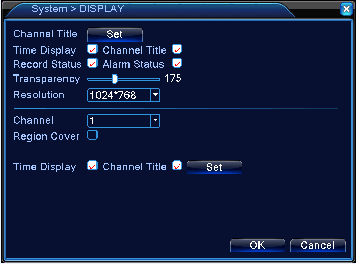
Set the position of the Time Display and Channel Title on IE and APP Access screen
【Channel Title】Click on the Set button to rename each channel camera.
【Time Display】The Date/Time display on the top right corner of the screen.
【Channel Title】This decides whether or not to show the Channel Title on each live view screen.
【Record Status】This decides whether or not to show the recording icon on each live view screen.
【Alarm Status】This decides whether or not to show the alarm icon on each live view screen. The alarm function is NOT supported by SANSCO DVR because it does not have Alarm In/Out.
【Transparency】Adjust the transparency of the screen background.
【Resolution】Set the DVR resolution output.
【Channel】Choose the channel camera from the drop-down menu to set up the Region Cover, and the position for Time Display/Channel Title (on IE/mobile app view).
【Region Cover】Set up the region cover for any channel camera(s) based on your preference. Check the box first, then choose the desired channel(s), and click the Set button to enter the screen for setting up the region cover. The region cover will appear as Black Patch on the live view screen.
【Time Display】【Channel Title】You can choose the channel from the drop-down menu, then check the boxes for Time Display and Channel Title, click Set button to enter next screen, from there you can adjust the positions for both the Time Display and the
Channel Title, you can left click and drag to move the position, then right click to exit, click OK to save and exit. These changes will not reflect on the live view screen, they will reflect on the IE view screen, and the app view screen.
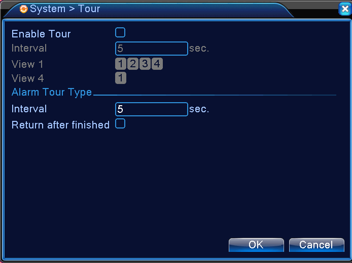
4.4.8 Tour
Enable the Tour, and set up the time interval for the camera from point to point. You can set up quad-cam view/single-cam view
Set up the time interval for the Alarm Tour. Check the box for “Return after finished” to make sure the camera return its original angle after the tour.
Note: In the Tour Preview, click to turn on the tour, click
to turn it off.
4.4.9 Digital (Take 4-Channel DVR for example)

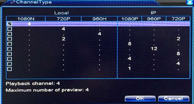
Because the DVR support different kinds of camera, you can change the combination of the Analog and IP cameras here to allow you to connect different types of cameras into the DVR. This is also called the Channel Type on the menu.
Examples: If you check the box for the first line, it means you can connect up to 4 1080p cameras and 0 IP camera. You can also read the explanation below for more information.
Under Advanced Menu, there is: Storage, Account, Online User, Output Adjust, Auto Maintain, Restore, Upgrade, Device Info., and Import/Export.
You can manage your hard drive or check the hard drive information here.
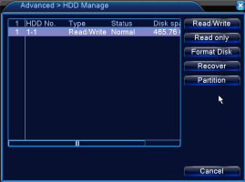
Read/Write: Set the hard drive properties to read and write. Read only: Set the hard drive properties to read only.
Redundant (For some models): Set the hard drive properties to redundant. (Refer to 4.2.1 Record Config. – [Redundant]).
Format Disk: You can format the hard drive when there is any error message related to storage, i.e. stop recording, hard drive error. Recover: Recover any potential error in the hard drive.
Partition: Partition your hard drive. Click on it to go to HDD partition. Two types of partitions: Record Partition, Image Partition. Note: Please format the hard disk before record.
You can manage the groups and users under this Account setting.
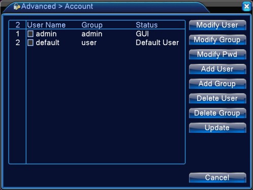

How to add user?
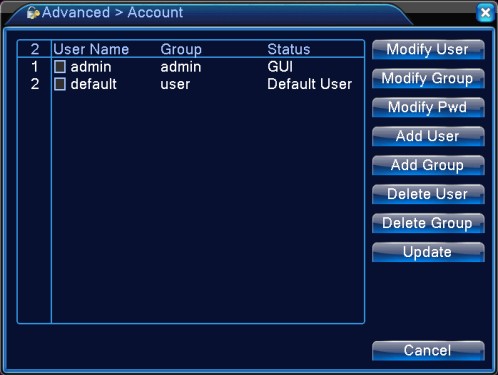

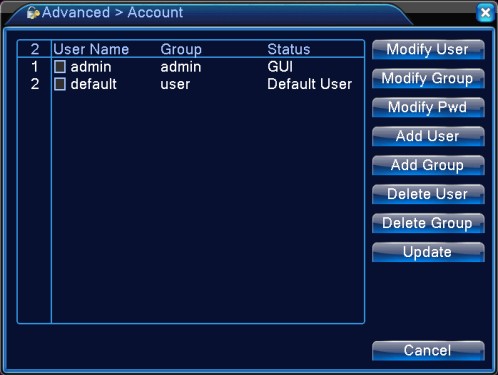
How to add Group?
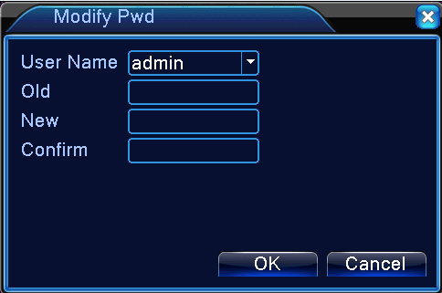
How to modify password?
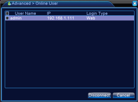
You can check all users who are connected to the DVR from Online User. You can choose any user(s) and click disconnect to stop the connection, if you do this, the user(s) will be able to log into the system again only after you reboot your DVR.
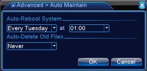
User can schedule the time for automatic system reboot, or automatic deletion on the old recorded files.
The user can reset the settings back to default. You can reset all the personal settings, or you can choose some of the settings and reset them back to factory based on your preference/needs. Check the box and reset them.
You can normally reset the system when there are problems with the settings, or you forget the login password, etc.

User can upgrade the DVR firmware version by using a USB memory stick, obtain the upgraded file from us and copy the file to the memory stick, insert the USB memory stick to the DVR via USB port, and go to Main Menu – Advanced – Upgrade to upgrade the system.

【Upgrade】Choose the USB memory stick that contains the upgraded file.
【Upgrade file】Choose the upgraded file.
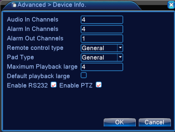
The Device Info shows the basic information of the DVR interface (i.e. Audio In Channels, Alarm In/Out Channels, Max. Playback, etc). You can set some of them per your preference.
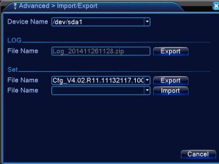
Users can not only export the logs and the configure files from the DVR to a USB memory stick, but also import those configure files from the memory stick to DVR settings. Pay attention to the file format before you Import and Export.
Under the Info Menu, there is HDD Info, BPS, LOG, and Version.
The HDD info includes Type, Capacity, Capacity Left, and Status.

x means the hard drive is faulty/problematic.
– means no hard drive detected.
Display the Bit Rate (Kb/S) and the spaced used (MB/H) in real time.
You can search the logs based on the Type, Start Time/End Time.
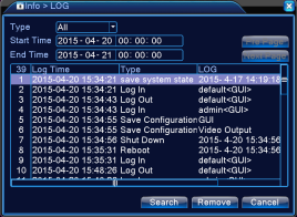
Log information includes: Log in/out, Shut Down, Reboot, Save Configuration, Recording, User Management, and many more related to the operation of the DVR. You can search the logs (based on the Type/Time) and clear them all by click the Remove Button.
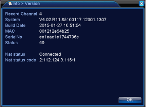
The Version displays the hardware information, software version, Mac address, Build Date, Serial Number, and NAT status.
Question: Can’t log into the DVR from the internet?
Answer:
Cloud users
If using the cloud, check to see if the DVR serial number typed in is correct. Check to see if the mobile device is connected to data. Try using Wi-Fi. On the DVR itself go to System > NetService and check the cloud status. It should say “Connected”. If not, check the network cable.
Make sure the DVR can be accessed locally via computer. If you can only access the DVR locally, the cloud may be busy and you can try again. If local access fails, see step 2. Close the mobile app and open it again. Test with another mobile device.
Non-cloud users (port forwarded) (We do not recommend you use the Port Forwarding as it is more complicated.)
Check the address bar to verify you are using the correct IP address and port number. Check every single digit because typos can be common. The address should start with “http://”, followed by the external IP address, followed by the colon symbol and the port (“:8888”). Try another web browser to see if you can get a login. Make sure that any software firewall or hardware firewall is not blocking ports 8888. Check for any port restrictions imposed by the router on both the DVR side and the remote computer side. Check all relevant settings including port filtering and application exception lists. Double check that the port and local IP addresses of the DVR are assigned for forwarding on the router. If you were previously able to access the DVR from the outside, make sure that the external IP address specified in the address bar is still valid (the router’s external IP address may change from time to time.) If using Dynamic DNS, make sure your account has not expired or test with the DVR’s current external ip address instead of the host name. Double check the settings on the DVR. Make sure the DVR can be accessed locally. If you can access DVR locally but not remotely, there is a problem with port forwarding. Review your router port forwarding settings. Review the router manual. If the router is attached to another router upstream, you will need to do port forwarding from the upstream router to the current router (using the current router’s local ip address on the upstream router, and ports 8888). If you have changed routers, make sure the local static IP on the DVR is still valid for the router is it connected to?
Question: No local network access to the DVR?
Answer: Make sure the computer is on the same router as the DVR. You can use the “ping” command from the command line (ie “ping 192.168.1.112”) to see if the DVR is accessible at all. Ping the local IP address that was assigned to the DVR. You should see response times from the DVR (no timeouts). If you get response times, you can log in locally using a web browser. If you get a timeout, reconnect the DVR’s network cable on both ends, or test with another cable. Most network cables will snap in. You may also power cycle the DVR. Check network lights on the router and on the DVR network port. Try connecting to another physical port on the router. Make sure the DVR is using a unique local IP address. Check the validity of the IP address assigned on the DVR. Some routers have a numeric restriction on the range of local addresses (you may need to reassign a static address to the DVR.) Make sure you log in with the correct local IP address and port. Check every single digit because typos can be common. Go in the DVR menu and verify the assigned address numbers. Recheck your assigned web port and media port. Check firewall settings. Try adding the DVR local IP to the local zone (Internet Options > Security > Local intranet > Sites > Advanced > Add > Close > Apply > OK). Use another web browser. Access the DVR from another computer on the same router. Test the DVR with another router. If you have changed routers, make sure the local static IP on the DVR is still valid for the router is it connected to? Reboot the DVR.
Question: I don’t have internet connection, is it required for my setup?
Answer: If you do not have internet connection, you can only view the cameras on your Monitor/TV, but not your mobile devices. You will not be able to access the cameras remotely via internet, either.
To access the DVR menu or the live view interface, please follow the Connection Diagram under Section I, connect all the cables (except step 5), and you will be able to view all cameras on your monitor/TV, you can then make changes, or configure the DVR/camera settings on your screen.
Question: No picture on monitor / TV after connecting it to the DVR
Answer:
Question: I want to access the cameras on my APP, but I am unable to find the SN Code/SerialNo for the device?
Answer: On the DVR Menu, right click your mouse – Guide – Next – Next – Next – SN Code. Scan this code on your APP.
Alternatively, you can go to Main Menu – Info – Version, and find the SerialNo. You can then manually enter the Serial Number to your APP. Please refer to the Section III [Mobile Viewing] – How to Find the QR Code or the Serial Number for the Device?
Question: My DVR is making a cracking noise
Answer: This normally happens for DVR with hard drive, if your DVR does not include a hard drive, please skip.
Question: The night vision of my camera is terrible?
Answer:
3. Light up the ambient area a little bit, in complete darkness, the night performance may be affected.
Question: My camera is getting misty inside, is there a known fix?
Answer: Condensation occurs in a humid environment as a result of the difference of the temperatures of the air and the object on which it occurs. In most cases it will clear up itself. The mist is more or less a rapid drop in temperature – one solution might be the use of a see-through rain cover, or a large enough ziplock bag with appropriate cuts, applied before taking the camera out of doors to minimize the humidity trapped in it. Otherwise, the same humidity will still condense within the rain cover itself instead of in the camera just like when one uses a rain cover in cold weather with a warm camera. Another, not as practical, but effective solution might be to regulate the temperature around the camera, but isolating it from humidity is the more guaranteed solution, even if it is only applicable in very few situations. If the issue remains, you may send it back for replacement, please contact us via email.
Question: My DVR is not recording, why?
We sell DVR with / without hard drive, so make sure your DVR come with a preinstalled hard drive. If your DVR does not include a hard drive, you can source one on your own, or you can purchase one from us. If you have a spare hard drive and you can install on your own, make sure it is a 3.5 inch internal HDD with SATA connector.
Question: I’ve forgotten the login password for my DVR and I can’t log in, I am locked out.
We have super password for your DVR, you can email us with the following information and we will send you a unique password: Your model number, the date/time display on your screen. Password varies from date to date.
Question: My remote is not working?
Question: Does the DVR record audio as well?
Answer: By default, the cameras do not have audio recording function, if you wish to record audio you will need to install additional devices, i.e. microphone, speakers, microphone for Audio IN, speaker for Audio OUT.
Question: How to set up email notifications for my DVR?
Answer: Make sure the DVR is connected with the router, and the Cloud Status is Connected. Go to the following screen:
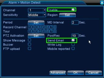
Check the box for Enable. And check Send Email. Refer to 4.4.4 NetService – EMAIL for more information on setup.
Question: How to set up motion detection recording?
Answer: The DVR needs an internal hard drive for recording. Without a hard drive, it will not record. And you can only live view if you do not have a hard drive. Please go to Main Menu – Advanced – Storage to check if the hard drive status. If the hard drive is
there and working, find the steps below:
Step 1 Go to Record Config., choose the Channel, then choose Schedule and check the box for Detect.
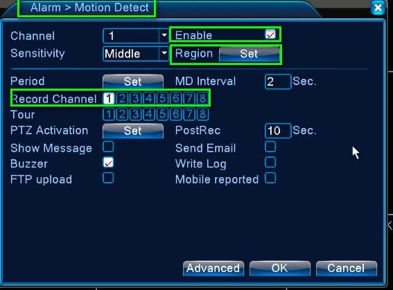
Step 2 Go to Alarm – Motion Detect. Check Enable, Set the motion detection Region if you like, and check the Record Channel (the channel you want it to record upon movement detection). Click Ok to save the settings and exit.
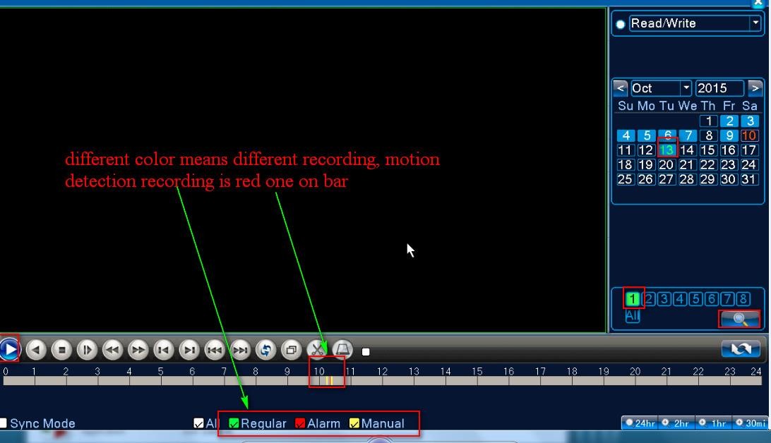
Step 3 Find the motion detection recording in Playback (3.5.4 Playback):
Question: How to connect your DVR on the client software CMS?
Answer: Make sure your DVR has been connected with the router and the NAT Status is Connected. [Main Menu] – [Info] – [Version] – [NAT Status]
Step 1 Download the software CMS and install it on your computer.
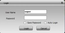
Step 2 Double click on the icon to run the CMS, the default username is super, no password.
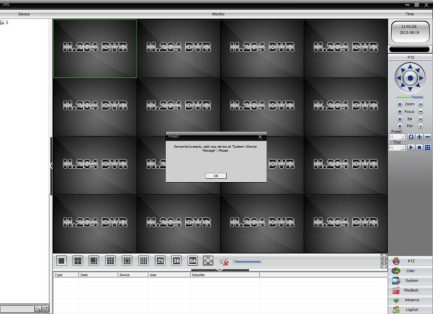
Step 3 If you log in for the first time, you will see the following screen:
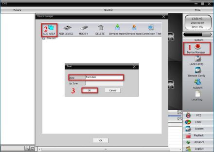
Step 4 To add your DVR, you can click System on the bottom right corner of the screen. Then go to Device Manager, click ADD AREA to create a zone. Name the zone and click OK.
Step 5 Left-click the area you created, then left click again on to add your DVR. Device Name: Name the device
Login type: Choose Cloud
Serial ID: Find the Serial ID (SerialNo) of the device per the manual instruction – Section 3.5.2 Guide. User Name/Password: Default is admin and no password, same as your DVR login account.
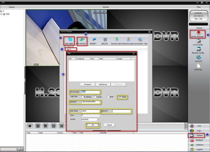
Click OK to save the settings. After that, you can double click on the device to access the DVR.
After you add your DVR successfully on CMS, you can then view or manage your DVR.
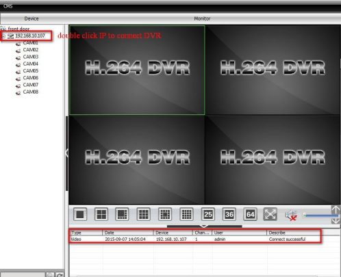
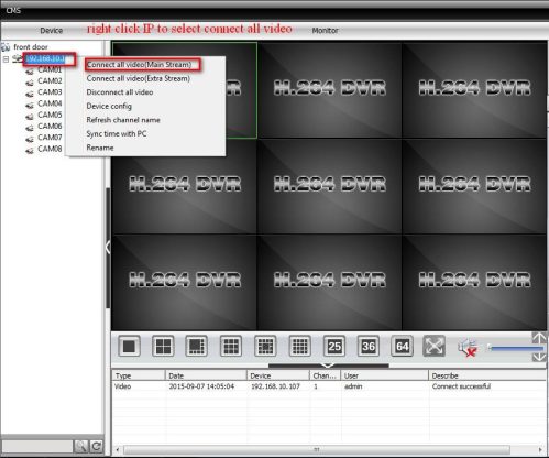
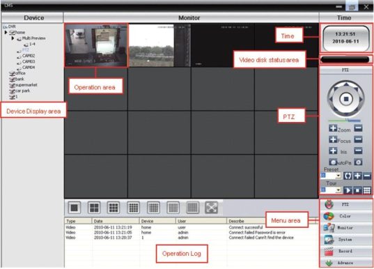
CMS interface


When Itried to connect to my NVR I get the comment that the user is blacklisted.
I can’t get rid of that one and I am excluded out of the configuration.
With tv and camera’s it workes fine but not networked.
Any solution?
Hello, you need to reset the device to factory default. To do this, go to main menu/tools/default/all.
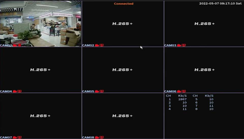
Hola sin querer toque algo en el menú y ahora la cámara n1 no se ve. las demás si se ven bien pero esa no se ve y me aparece en los iconos pequeños en la ventana una Px es decir una pcon una x roja al lado. Trate de reiniciar a los ajustes de fabrica y no se quitó. Será que podrían ayudarme por favor