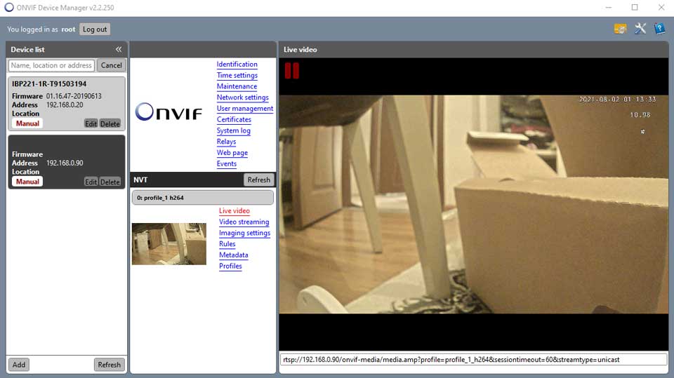
Onvif Device Manager Complete Installation Guide, ONVIF Device Manager is a software application used to administrate network video servers and cameras within CCTV systems. The User Guide describes the product installation, video encoder, network and analytics configuration, the software update and troubleshooting. Thus, the document is intended for the personnel responsible for administrating CCTV systems and separate network video surveillance devices with the help of ONVIF Device Manager.
• Windows XP SP3 operation system (or higher; Windows 7 recommended)
• Microsoft .NET Framework 4
• 1 Gb RAM (2 Gb recommended)
• 40 Мb of free drive space
.
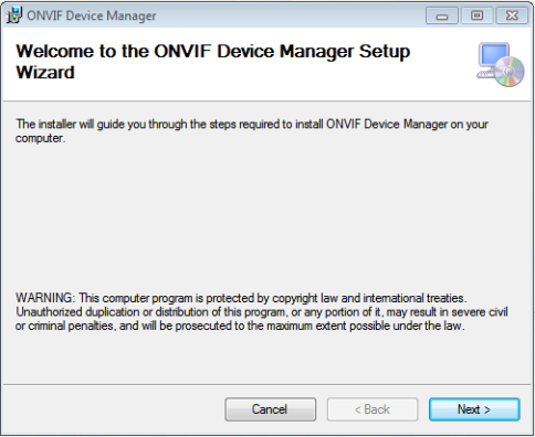
1.1ONVIF Device Manager Setup
.
Setup Wizard will check if Microsoft .NET Framework 4 is installed to the computer. If it is absent, the following message is displayed.
Onvif Device Manager Complete Installation Guide
Read More : DW Spectrum Full User Guide
![]()
.
4.Download dotNetFx40_Full_setup.exe and install .NET Framework according to the setup instructions.
5.After Microsoft .NET Framework 4 setup run onvifdm.msi again.
6.Windows User Account Control may ask for the permission to continue the installation. Click Yes.
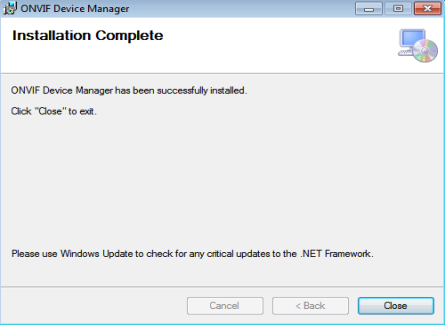
7.To complete ONVIF Device Manager installation process, click Close.
1.2Starting ONVIF Device Manager
1.Launch ONVIF Device Manager from he desktop or Start menu.
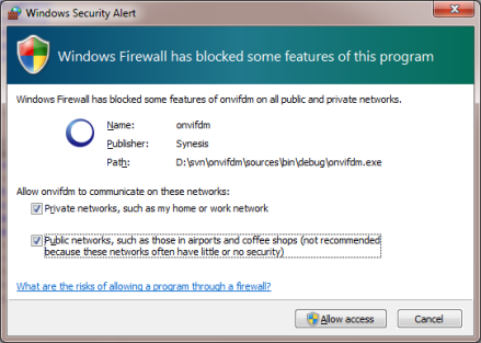
2.During the first launch, Windows Firewall may ask for the permission to open access to the network for onvifdm.exe. Click Allow access.
.
3.After ONVIF Device Manager has been launched, your device is automatically detected and displayed at the end of the device list on the left. If the device has not been detected automatically, check the connection and click Refresh.
.
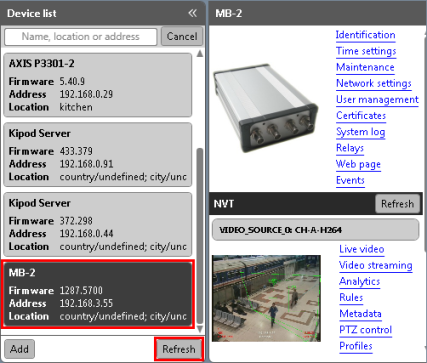
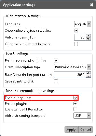
4.To make sure the device is selected correctly, check live video snapshots from the active video channels. If the snapshots are not displayed, check Enable snapshots in Application Settings (![]() button).
button).
2.1Video Server Identification
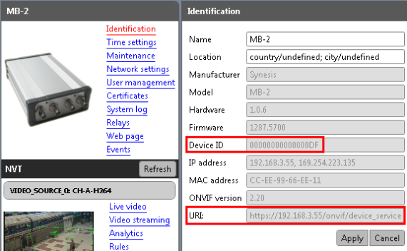
2.Select Identification at the top of the menu list.
3.Check that Device ID value coinsides with its serial number.
4.Fill in Name and Location fields.
5.Click Apply. Your settings are saved.
.
![]() Identification tab contains URI parameter necessary for connecting the device to a video management system.
Identification tab contains URI parameter necessary for connecting the device to a video management system.
.
For correct functioning of access management system, it is necessary to synchronize the time on the device and on the user’s computer. If the device is equipped with a real-time clock with independent power supply, the time is synchronized automatically.
For video servers and cameras not equipped with an RTC-clock or independent power supply, it is necessary to select Synchronize with NTP server option. Otherwise, in case of power cut the time on the device is reset, and it is impossible to access the device from the PC.
![]()
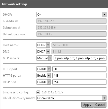
Select Network Setting from the device menu. By default, the settings are the following.
.
2.3.1Settings for a Network with DHCP Server
Nowadays, most networks are equipped with a DHCP server which automatically assigns an IP-address to devices connected. In this case fields IP Address, Subnet Mask and Default Gateway are filled automatically and uneditable.
1.Host name, DNS and NTP servers can either be received from DHCP or entered manually. Select the option you need.
2.After all the settings are selected, click Apply.
3.Wait until the devise reboots.
2.3.2Settings for a Network without DHCP Server
If the network has no DHCP server, the device IP address is determined automatically via ZeroConf protocole (Enable zero config option is checked by default).
1.In computer’s network settings select Receive IP address automatically. (If a static IP address is selected, the video server will not be shown in the device list as belonging to another network).
2.In order to assign the device a static IP address (eg., in a network without DHCP server), select Off in DHCP dropdown. After that fields IP address, Subnet mask and Default gateway are possible to edit manually.
3.Fill in fields Host name, DNS and NTP servers manually.
4.Specify other settings and click Apply.
5.Wait until the device reboots.
2.3.3Discovering device in a network
To make device function without being discovered in the network, select non discoverable option as ONVIF discovery mode.
To make it visible in the list select discoverable.
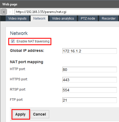
In most cases a video analytical device is connected to a local network and has a local IP address. In order to get access to the device beyond the local network, or to connect it directly to the Internet, the following settings are necessary.
1.Go to Web page to Network tab.
2.Check Enable NAT traversing.
3.Enter Global IP address.
4.Specify NAT ports and click Apply.
ONVIF Device Manager supports the following types of users.
Anonymous user is not registered in the system and, therefore, can have unlimited access only to those devices from the list where no users from other categories (“user”, “operator”, “administrator”) are registered. On the devices with at least one abovementioned user, anonymous user has right only to view time settings.
Administrator has access to all application sections and features, the rights to reboot the device, reset the settings and update the firmware, create other users with different access rights.
.
![]() The first user on the device must be created as Administrator.
The first user on the device must be created as Administrator.
For the differences in Operator’s and User’s access rights (by default), consult the table on the following page.
CHANGE – the right to change current and create new settings.
VIEW – the settings are not hidden, but it is not permitted to change and create them.
HIDDEN – Certain settings or even the whole section is hidden.
.
|
Application section or feature
|
Operator
|
User
|
|
Identification
|
VIEW
|
HIDDEN
|
|
Time Settings
|
VIEW
|
VIEW
|
|
Maintenance
|
.
|
.
|
|
Configuration backup
|
HIDDEN
|
HIDDEN
|
|
Configuration restore
|
HIDDEN
|
HIDDEN
|
|
Soft factory reset
|
HIDDEN
|
HIDDEN
|
|
Hard factory reset
|
HIDDEN
|
HIDDEN
|
|
Device Reboot
|
CHANGE
|
HIDDEN
|
|
Firmware update
|
HIDDEN
|
HIDDEN
|
|
Network Settings
|
VIEW
|
VIEW
|
|
Users
|
HIDDEN
|
HIDDEN
|
|
Certificates
|
VIEW
|
VIEW
|
|
System Log
|
HIDDEN
|
HIDDEN
|
|
Relays Settings
|
CHANGE
|
VIEW
|
|
Web Page
|
CHANGE
|
.
|
|
Events (including filter management)
|
CHANGE
|
CHANGE
|
|
Live Video (including rtsp-link)
|
CHANGE
|
CHANGE
|
|
Video Streaming
|
CHANGE
|
VIEW
|
|
Analytics
|
.
|
.
|
|
Object tracking
|
CHANGE
|
VIEW
|
|
Depth calibration
|
CHANGE
|
VIEW
|
|
Service detectors
|
CHANGE
|
VIEW
|
|
Antishaker
|
CHANGE
|
VIEW
|
|
Annotation settings
|
CHANGE
|
VIEW
|
|
Rules
|
CHANGE
|
VIEW
|
|
Metadata
|
CHANGE
|
VIEW
|
|
Profiles
|
CHANGE
|
VIEW
|
|
Settings (Kipod Server)
|
CHANGE
|
VIEW
|
1.![]() To create a new user go to User management tab and click Create.
To create a new user go to User management tab and click Create.
.
.
.
.
.
.
.
.
.
.
.
.
.
2.![]() In the next window specify User name, password (2 times), and his role in the system (administrator, operator or user). Click Apply.
In the next window specify User name, password (2 times), and his role in the system (administrator, operator or user). Click Apply.
.
.
.
.
.
.
.
.
![]() The first user on the device must be created as Administrator.
The first user on the device must be created as Administrator.
.
The following message is displayed, and the user is added to the list.
![]()
.
To edit user data, use Modify button. To delete a user, click Delete.
1.After launching ONVIF Device Manager, enter user name and password in the corresponding fields at the left upper corner of the window.
![]()
.
2.To remember login and password for the next application launch, check
Remember before logging in.
2.4.3Viewing Device User Data
Administrator can view the data about device users.
2.Select Access as log type and click Get.
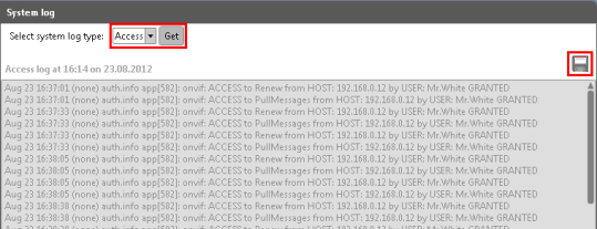
3.To save the log to a separate file use Save button at the right corner.
2.4.4Changing Default User Settings
The list of rights assigned to each user category is possible to edit. For this purpose, device settings are saved in a text file containing program code. The file is edited and imported back to the system.
We strongly recommend that this operation is fulfilled by qualified personnel or our customer service specialists.
1.In order to save the current user settings to a file, go to User Management
tab.
2.Click Backup in Policy section. File save dialogue will open to save the current settings to a .txt file.
![]()
.
3.Edit the file the way you need.
4.In order to upload the edited file, click Restore and select the file on your hard drive.
Safety certificates allow you to transfer data via a safe connection.
1.To upload a certificate click Upload.
2.Select the certificate file from your hard drive (.pem).
3.Enter certificate name and click Upload Certificate.
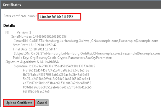
4.Check the certificate and click Apply.
![]()
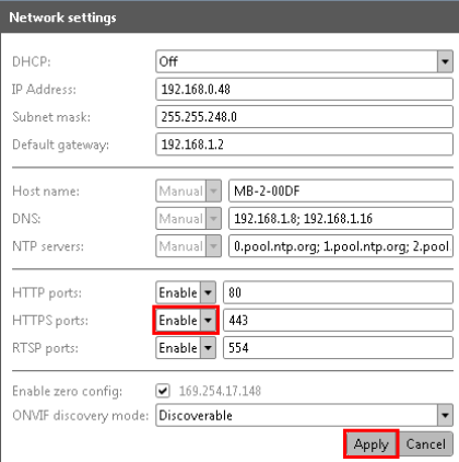
5.For the correct functioning of the certificate, go to Network Settings and enable HTTPS protocole.
6.Click Apply to save the settings.
.
2.5.2Deleting a Certificate
1.Disable HTPPS protocole in network settings.
2.In Certificates tab check the certificate and click Delete.
2.6Relays Settings (optionally)
Relays tab contains information on all the relays connected to the device.
.
![]()
.
To configure a relay, perform the following actions:
1.Select a relay from the list on the left.
2.Set relay mode, idle state and delay time.
To activate or deactivate the relay use the corresponding button.
The appearance and functionality of the web page depends on the device connected and its manufacturing company. For this reason, this section cannot be described within the current document.
Functionalities of devices by Synesis represented on the web page are described in relevant sections of the User Guide.
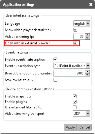
To open the web page in a separate browser, check Open web in external browser in Application settings (![]() button).
button).
2.8Recording to a Removable Storage Device
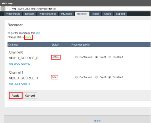
1.Go to Web page to Recorder tab.
.
2.Connect a USB storage device to the video server and wait until its status changes to Ready.
3.Select recorder activity type for each video channel: Continuous or Event.
Continuous recording is performed in continuos mode regardless to video analytics events. When the removable storage memory is full, the oldest recordings are removed automatically, releasing space for the newer ones.
Event recording is triggered by a video analytics rule, pre- and post-recording time comprising 10 seconds.
4.If one of the channels does not require recording, select Disabled in
Recorder activity.
5.Click Apply to save the settings.
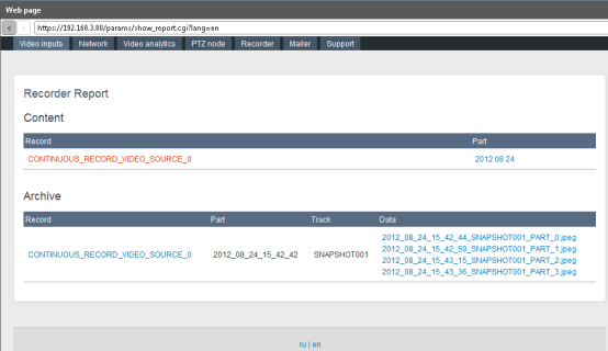
To get the recorder report, use the link in the upper line.
2.8.3Sending Recording Notifications
The system allows sending notifications about the recording to an e-mail specified.
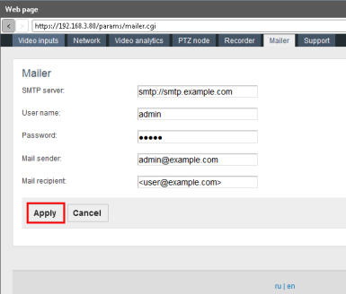
1.To confugure notification sending, go to Mailer tab in Web page.
2.Specify SMTP server name, user name and password (the same as for sender’s e-mail), mail sender and recipient.
3.To save the settings, click Apply.
This section allows viewing all the events registered by the device in text mode.
1.To enable Events section on the device, check Enable events subscription in Application settings (checked by default). To access Application Settings, click ![]() .
.
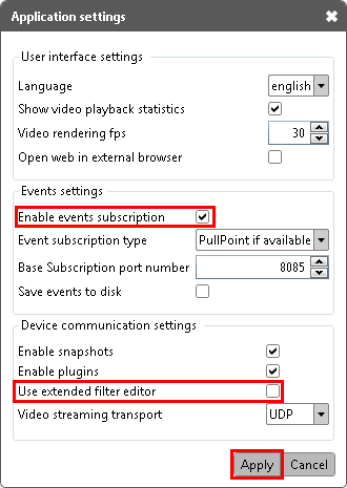
2.From the dropdown select event subscription type. By default PullPoint if available is selected.
3.Selecting Only Base Subscription, specify port number.
4.To save the settings, click Apply.
2.9.2Metadata Configuration
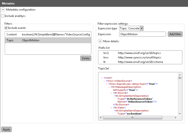
To optimize separate events search, the application supports Metadata Configuration.
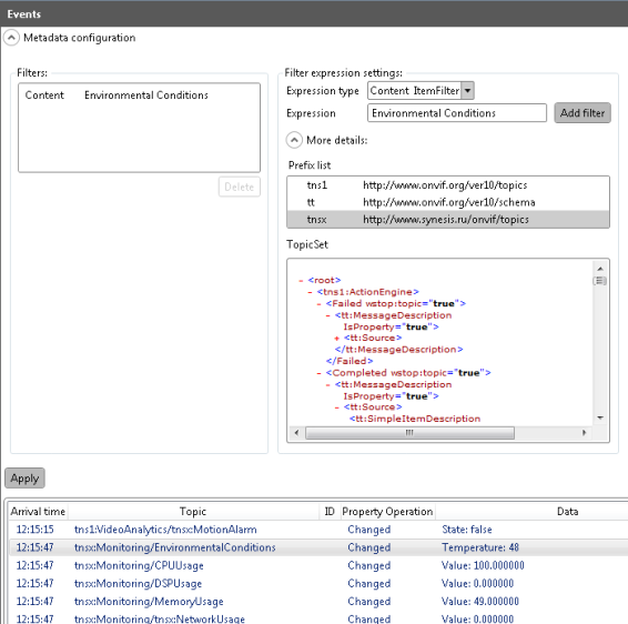
1.In filter expression settings select expression type and enter the expression
to create a filter.
2.Click Add filter. The filter will appear in the filtes list on the left.
3.To specify the filter details unfold More details section.
4.In Prefix list only those prefixes are available which are used in the current
.xml document. In order to be able to create prefixes manually, check Use extended filter editor in Application Settings (![]() , see the previous picture).
, see the previous picture).
For detailed filter management rules consult ONVIF specification http://www.onvif.org/specs/core/ONVIF-Core-Specification-v220.pdf, chapters
9.5.5 and 9.7.3.
The application provides several video transmission settings, common to all the devices connected.
1.Check Show video playback statistics to display this parameter within the video frame (frame per second frequency for rendering and decoding).
![]()
2.In order to enable this option, check it in Application settings (![]() button).
button).
3.Set Video rendering fps.
4.From the dropdown select Video streaming transport. This parameter denotes, via which protocol ONVIF Device Manager receives video stream from netwok video transmitter (NVT).
5.Set the necessary values and click Apply.
.

3.2Additional Settings (optionally)
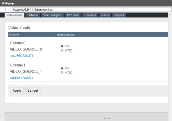
The application allows choosing video standard for each channel. For better video reception quality, the standard on the channel and on the video camera should coincide. For example, the camera transmits analogue video via NTSC. For correct video reception, it is necessary to set NTSC video standard on the receiving channel.
1.To configure video channels, go to Web page, Video inputs tab.
2.Select video standard for each channel (PAL or NTSC) and select Apply.
3.3Channel Configuration (optionally)
1.Go to Settings of the selected video channel.
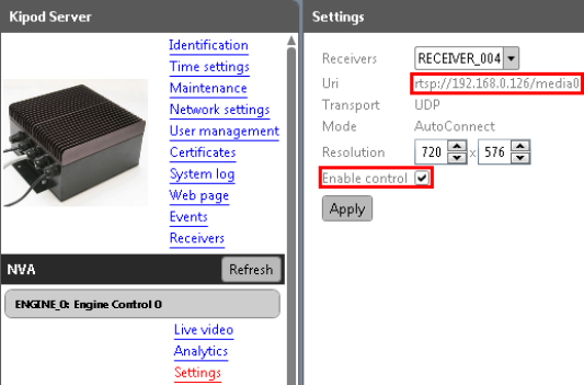
2.Select the receiver from the dropdown.
3.In Uri-field paste rtsp-link to the video, copied from the network device transmitting or processing live video (IP-camera, video-encoder).
4.Specify video resolution.
7.Go to Live video section.
Here you can see the video, the link to which you have specified.
3.4Video Streaming (optionally)
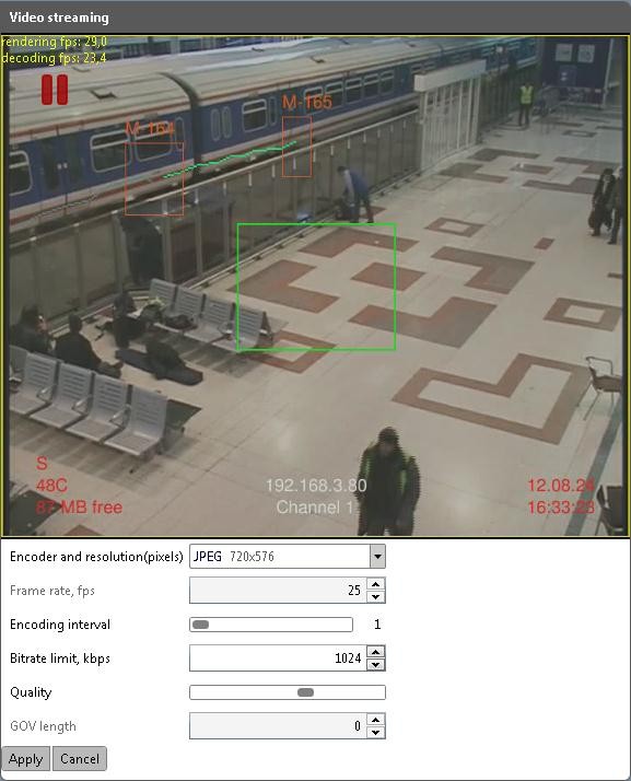
This section allows you to configure the following parameters of displaying video:
Encoder and resolution (pixels) of the video (selected in the dropdown).
Frame rate (frame per second) denotes how many frames per second are captured by the video camera connected to the device. This parameter is uneditable and shown just for information.
Encoding interval (number of frames) denotes at which rate the frames coming from the camera are encoded. For example, when encoding interval comprises 25, it means that 1 frame from 25 captured per second is encoded and transmitted to the user. The maximum value reduces the load to the channel, but may cause skipping information from the frames that were not encoded. Reducing encoding interval will increase the frequency of picture update, as well as the load to the channel. The parameter is set with the help of slider bar.
Bitrate limit (kbps) is the amount of information required to play one second of video. The less the bitrate is, the less the final video file size will be. But when the bitrate is considerably reduced, the program will have to use stronger compression algorithms, which reduces video quality, too. The value is entered manually or with the help of spin box.
Quality is the parameter which enables to reduce the load to the channel by means of reducing the picture definition. The parameter is set with the help of slider bar: the left most position corresponds to the highest picture definition, the right most to the lowest load to the video channel.
GOV length is possible to edit only in case the encoder is Н264. This parameter denotes the length of picture group between the two key frames. The higher this value is, the less is the load to the network, but the quality of the video is affected. The value is entered manually or with the help of spin box.
.
.
Set the necessary values and click Apply.
4..Video analytics Configuration
4.1Default Annotation and Analytics Configuration.
ONVIF Device Manager has default annotation and analytics settings and is ready to use with any device. It is possible to view the settings with a double- click on Annotation Module Default Annotation and Analytics Module Default Analytics respectively.
To modify analytics module, click on Analytics Module Default Analytics and then click Modify.
![]()
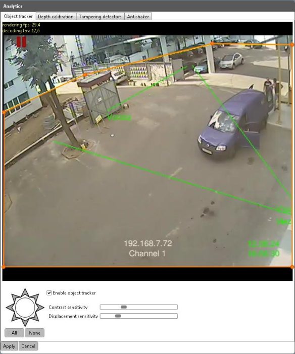
4.2Object Tracker Configuration
.
1.Specify the region where object tracking should be applied. For this, move the sides of the red rectangle by dragging its corners with the mouse left button.
2.In order to create additional corners, double click on one of rectangle sides in any place. Holding mouse left button, move the new point to the necessary position until a new polygon corner is formed. The same way create other polygon corners.
3.Position the polygon so that its borders correspond to the tracking region.
4.Check Enable object tracker to make other parameters editable.
5.Set necessary contrast sensitivity by moving the slider. This value denotes how contrastive an object should be to be detected against the backround. For example, at high contrast sensitivity a peson in dark clothes is more likely to be detected against dark background.
6.By moving the slider, set displacement sensitivity. It denotes which distance a person or vehicle should cover in the video to be detected as a moving object. At high displacement sensitivity, a short distance is enough for detection.
7.Video analytics can be configured to track only objects moving in a certain direction. For this, select the directions you need at the octangular figure on the left. The selected directions turn gray after a mouse click.
8.To select all the directions at once, use All button. None button diselects everything.
9.To save the settings click Apply.
Calibration allows relating object sizes in the video with their real sizes. ONVIF Device Manager supports two types of calibration.
This calibration type requires specifying the following parameters:
• Marker real height, cm
1.Open Depth calibration tab in Analytics section.
2.Select Height Marker calibration type.
3.Select an object in the video that has equal height at its different parts (eg., a fence). It is important to measure the height from the ground.
4.Set both markers against objects of the same height (see the picture). Marker height can be changed by dragging its upper and lower points (the cursor assuming the form of a vertical arrow).
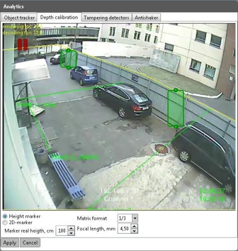
5.To move the marker, drag it to the necessary position with the mouse left button.
6.Fill in the necessary fields under the video: from the dropdown select matrix format, specify focal length and height of the real object related to the markers.
7.Save the settings by clicking Apply.
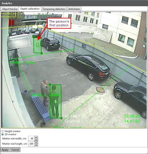
Does not require specifying matrix format and camera focal length. For this calibration type it is necessary to specify height and width of the real object (mm) shown in the video at different distance from the camera. The easiest way is calibration by a person’s picture.
2.The person stands within camera view in the background. The first 2D- marker should be positioned in such a way that vertically it corresponded to the person’s height and horizontally to the space he takes.
3.The first 2D-marker remains in the same position. The person moves to the foreground within camera view and stands in the same position as the first time. Place the second marker the same way as the first.
4.Fill in the parameters under the video: real object width and height (mm).
5.Save the settings by clicking Apply.
.
4.4Настройка сервисных детекторов
1.Go to Tampering detectors tab in Analytics section.
2.Check situations that require automatic notification.
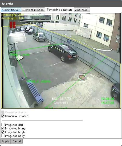
.
3.Save the settings by clicking Apply.
1.In Antishaker tab check Enable Antishaker.
2.In the video select a region containing typical scene elements against which the camera should be stabilized (road, columns, fence). For this, holding left mouse button move the blue rectangle corner points until it is reduced to a needed size.
3.Some moving elements like large vehicles and shaking trees can be present in antihaker zone. But it is highly recommended to exclude elements certainly not suitable for stabilization, like black video frame or the sky.
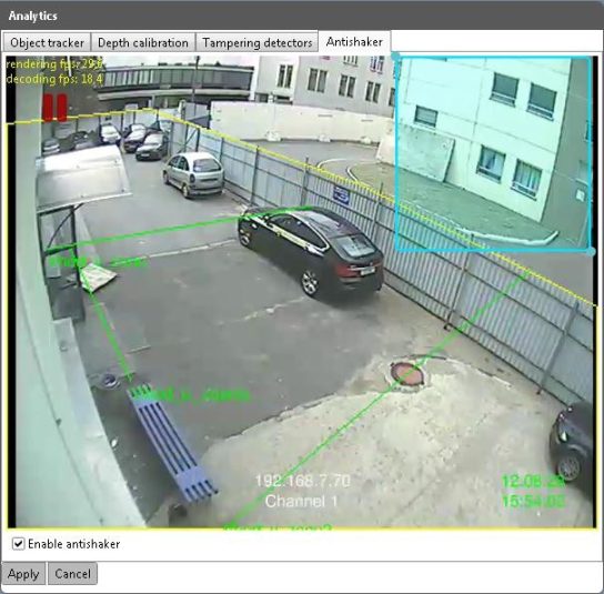
.
4.Save the settings by clicking Apply.
1.In Analytics tab in Available modules section select Annotation Module Default Annotation and click Modify.
2.In annotation window select elements to show in the video.
• Annotate system information
• Annotate calibration results
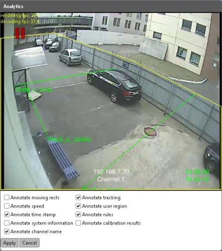
3.To save the settings, click Apply.
4.7Configuring Analytics in Text Format
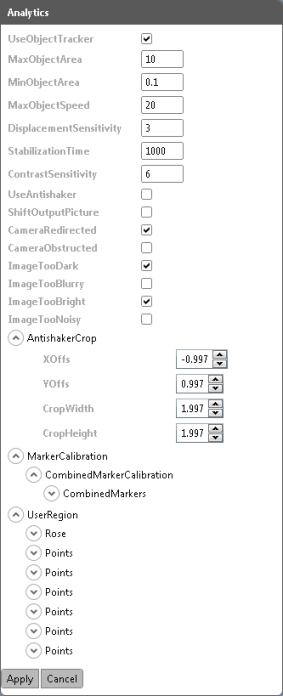 Alongside with the described ways of configuring analytics and annotation, the application provides an alternative way of configuring with disabled video plugins.
This way is used to configure analytics on devices by certain manufacturers, like Axis, or in case it is necessary to configure parameters absent in video plugin.
1.In order to enable this way of configuration, uncheck Enable pugins in Application settings (![]() button).
button).
2.Go to Analytics tab of the selected channel.
3.Check necessary options and set exact number values in the relevant fields.
4.Annotation and Rules are configured the same way with disabled plugins.
4.8Additional Video Analytics Settings
Besides configuration in manual or text format, the application supports analytics configuration via the file containing program code.
![]() It is strongly recommended that this type of configuration is performed by specially trained personnel, as incorrectly changed parameters can damage the system.
It is strongly recommended that this type of configuration is performed by specially trained personnel, as incorrectly changed parameters can damage the system.
.
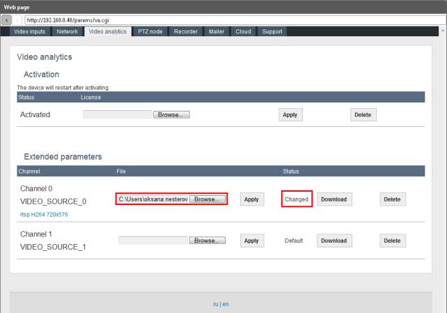
1.Go to Web page to video analytics tab.
2.In Extended paramenters section download the source file of each channel by clicking Download. The file is saved to your hard drive.
3.Edit the file the way you need and save the changes.
4.Click Browse on the relevant channel and select the edited file from the hard drive. Click Apply. The status will change from Default to Changed.
5.To remove the edited file from the system and restore the default settings, click Delete.
A tripwire rule means defining a tripwire in tracking zone, crossing which in one or both directions is regarded as an alarm event. For example, the tripwire is drawn in the driveway to the yard. An event is generated each time a person or vehicle come into the yard.
1.Go to Analytics tab of the selected video channel.
2.Click Create in Available Rules section.
![]()
3.In the next window specify the rule name.
4.In Type dropdown select Trip Wire Rule.
![]()
A video frame will open with a red line in the center of the screen. Here you can define the rule settings.
6.Move the line by dragging its end points until it reaches necessary length and position.
7.Define in which directions crossing the line is meaningful. For this purpose, click on one of the arrows in the middle of the line. When crossing the line in this direction, an alarm event is created. When both directions are selected (two arrows are marked), the event is registered in all the cases of crossing the line.
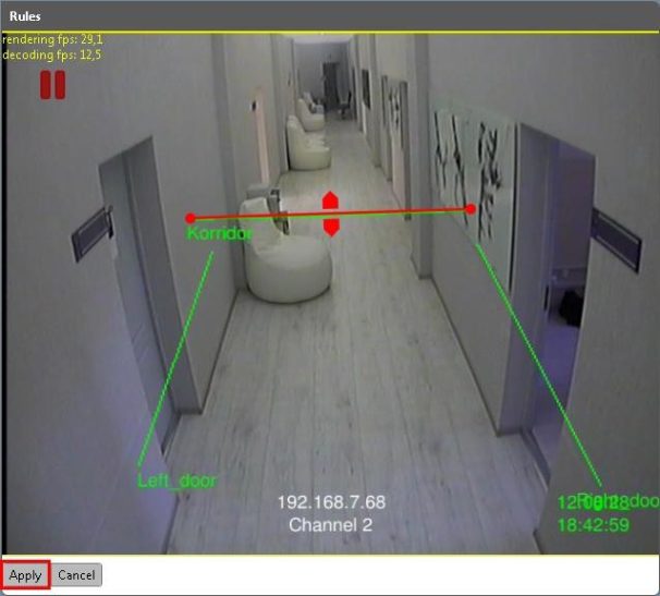
8.To save the settings, click Apply.
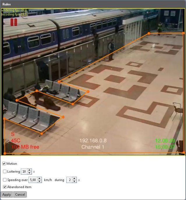
A region rule enables you to set a region and allow or forbid certain actions inside it. Depending on the settings, an alarm event is generated each time the rule is violated.
1.To create a region rule go to Analytics tab of the relevant channel.
2.Click Create in Available rules section.
3.In the next window specify the rule name.
![]()
4.In Type dropdown select Region Rule. Click Continue.
The video frame will open, where you can define the rule settings.
5.In the center of the frame there is a red rectangle. You can change its size and shape by dragging its corner points with the left mouse button until it covers the rule region (if the rule region is tetragonal by shape).
6.In order to add another corner (in case the rule region has the form of a polygon with five or more corners), double click on one of its sides in any place to form a new point. Drag it to form a new corner of the polygon.
7.Create other polygon corners and align its sides with the borders of the rule region (see the picture below).
8.Under the video check the options the analytics should react to in the rule region.
9.Motion tracks moving within the region.
10.Loitering means someone’s walking around a place during a certain time, or insignificant moving at a low speed. In order to detect such behaviour, check Loitering and specify its time.
11.To detect runnig within the region, select Speeding over… with specifying speed and time.
12.To generate an event when an object was abandoned withing the rule region check Abandoned item.
13.Save the settings by clicking Apply.
.
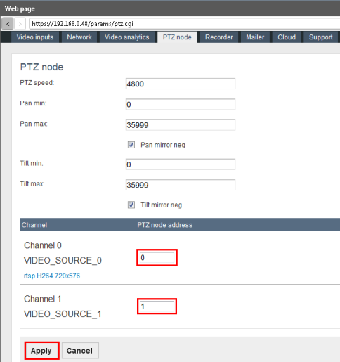
ONVIF Device Manager is optimized to control a Pan-Tilt-Zoom camera. While connecting the camera, follow the manufacturer’s instructions. The correctly connected camera is displayed in the device list.
1.Go to Web page to PTZ Node.
2.Default PTZ Speed including Pan min, Pan max, Tilt min and Tilt max
correspond to PelcoD standard. Change the settings, if necessary.
3.Specify PTZ-node address for each channel (number value). Zero value is also an address, it does not mean absence of device.
4.To save the settings, click Apply.
6.2Camera Movement Settings
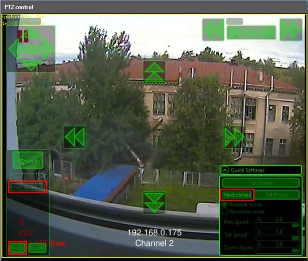
2.Adjust camera position with the help of arrow buttons in the center of the screen and zoom buttons at the right top corner. This view will be used as home position.
3.Open Quick Settings section in the right lower corner of the screen.
The camera will turn back to this position each time you click Home in the left part of the screen.
5.The same way set additional camera position. In Quick Settings section enter the name of the camera new position and click Set Preset. The preset is displayed in the list in the left part of the screen.
6.In order to set the camera in preset position, select it in the list and click Go to. The camera will automatically turn to this position.
7.In Quick Settings section set tilt, pan and zoom speed.
8.Select camera move type: relative or absolute. For absolute move the exact final position is specified, for the relative – the final position is calculated basing on the current camera position.
Profile is a complex of the following settings:
• Video Source Configuration
• Video Encoder Configuration
• Video Analytics Configuration
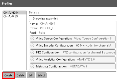
The application allows creating profiles of different configuration, eg., a profile without video analytics, only transmitting video, or a profile supporting PTZ configuration for a separate camera. Disabling unused functions helps unload video transmission channel. To change configuration, it is enough to select another profile without changing the settings manually.
By default there are two profiles for H264 and JPEG encoders.
1.To create a new profile, click Create in Profiles tab.
.
2.In the next window specify the profile name and check audio and/or video source configuration.
3.Configuration of the checked source will be included in the profile. Uncheck audio configuration to reduce the load to the channel (eg., in case your device does not transmit audio).
.
![]()
.
4.To continue profile configuration click Edit.
5.In the next window check profile components you need.
![]()
6.In the right column default configuration is described. To view and change default configuration settings, click on the gray button in the corresponding line.
7.In the left window highlight a setting and click Select. The details will show in the window on the left.
![]()
.
8.The same way select and configure other profile components. Click Apply.
9.After the profile settings are configured, select it in the list on the left.
.
![]()
.
All the profile components will appear in the configured channel menu.
10.To delete a profile from the list, highlight it and click Delete.
Metadata is text information associated with a video analytics event. To view it, open Metadata tab of the relevant channel.
In Metadata details you can view detailed information on the selected metadata fragment.
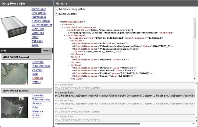
.
For Metadata configuration see the picture below.
For detailed rules of filter management consult ONVIF specification http://www.onvif.org/specs/core/ONVIF-Core-Specification-v220.pdf, chapters
9.5.5 and 9.7.3.
.
9..Maintenance and troubleshooting
This document provides only the easiest ways of troubleshooting. If you are not sure you will manage yourself, consult our support service (support@synesis.ru phone.+7 (495) 660-77-47)
Information on what may have caused the trouble in the application is contained in System log.
1.In order to get the information about the operations on the device, go to
System log tab.
2.Select System as log type and click Get.
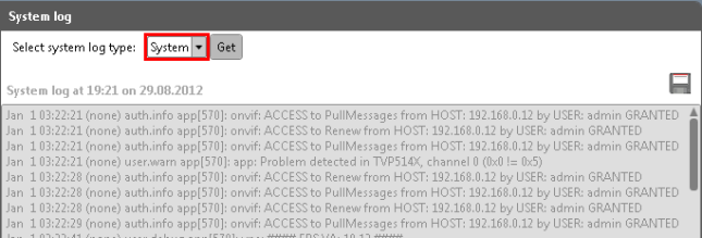
.
3.To save the information into a separate file (.txt) and click ![]() icon.
icon.
Configuration backup allows restoring the correct settings in case they have been damaged, reset or lost after the device break down. It is possible to back up all the settings, except video stream processing parameters that are stored in the form of profiles.
1.To save the current settings, go to Maintenance tab.
![]()
2.Click Backup in Configuration line. You will be offered to save the settings into a separate file with .backup extension.
When necessary, you can import the backup file with the help of Restore
button.
9.2Configuration Backup in Packet Mode
1.In order to restore configuration on several devices simultaneously, click ![]() button in the right top corner and select Batch settings restore (
button in the right top corner and select Batch settings restore (![]() button in Background tasks window).
button in Background tasks window).
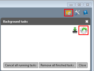
2.In filters select the device manufacturer, model and firmware version.
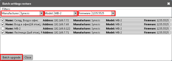
.
3.Check only the devices requiring settings restore and click Batch Upgrade.
4.In the next window select the backup file.
5.Settings restore will start in the background mode.
.
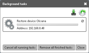
.
6.After the restore is completed, the following message will appear.
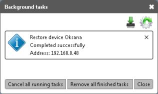
7.In order to clear the list, click Remove all finished tasks.
9.3Firmware Upgrade (for devices by Synesis)
9.3.1Firmware Upgrade for a Single Device
Firmware version is regularly upgraded and is available to download from Synesis website (http://synesis.ru/ru/surveillance/downloads).
1.Download a file from Synesis web-site (with .bin extension), corresponding to your device.
2.Click Upgrade at Maintenance tab.
![]()
The following message is displayed:
![]()
3.You can switch the process to the background or check automatically close when finished option.
4.After the process has been finished, the following message is displayed.
![]()
.
![]() Firmware update does not affect video analytics settings and other functions, so recurrent device configuration is not required.
Firmware update does not affect video analytics settings and other functions, so recurrent device configuration is not required.
9.3.2Firmware Upgrade in Batch Mode
ONVIF Device Manager allows upgrading the firmware in batch mode for all the devices connected.
1.Click ![]() icon in the top right corner to open Background tasks window.
icon in the top right corner to open Background tasks window.
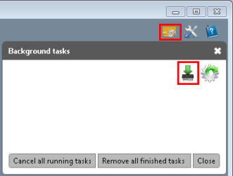
2.In Backgroud tasks click ![]() .
.
3.In filters select manufacturer and the model of devices to upgrade.
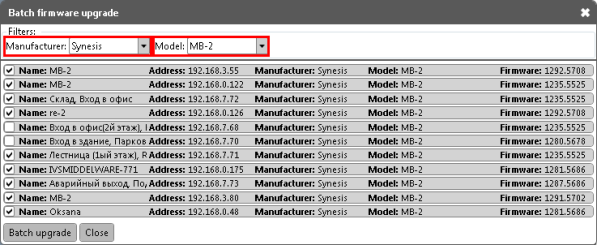
4.Leave checked only those devices in the list that reqire upgrade.
5.Click Batch upgrade. The upgrade will start in batch mode.
.
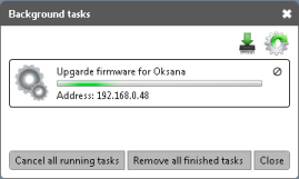
.
6.In order to cancel firmware upgrade, click Cancel all running tasks. After the upgrade is complete, the following message will appear.
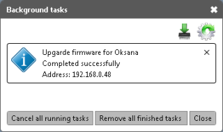
7.To clear the list, click Remove all finished tasks.
Device reboot can help repair insignificant faults of video analytics or other functions, caused by hardware failures. When you need to solve a problem with your device individually, it is recommended to reboot it first.
Click Reboot in Maintenance tab. The following message is displayed.
![]()
After the reboot the device appears in the list on the left.
During soft reset all except the network settings are discarded. Soft reset is applied in cases when the network is configured correctly, but the rest of the settings should be discarded.
![]() Click Soft Reset at Maintenance tab. After reset the following message is displayed.
Click Soft Reset at Maintenance tab. After reset the following message is displayed.
.
.
.
.
.
.
During hard factory reset all the settings are discarded. If your network settings do not coincide with the default application settings, you will have to configure the network again.
Click Hard Reset in maintenance tab. After the reset the following message is displayed.
![]()


Identification tab contains URI parameter necessary for connecting the device to a video management system.


The first user on the device must be created as Administrator.
The first user on the device must be created as Administrator.


button).


, see the previous picture).


 Alongside with the described ways of configuring analytics and annotation, the application provides an alternative way of configuring with disabled video plugins.
It is strongly recommended that this type of configuration is performed by specially trained personnel, as incorrectly changed parameters can damage the system.


Firmware update does not affect video analytics settings and other functions, so recurrent device configuration is not required.


Click Soft Reset at Maintenance tab. After reset the following message is displayed.
