Milesight CMS VMS installation user guide, Milesight Central Management System (CMS) is an intelligent surveillance solution for users to control up to 256 devices, to remote preview and playback more conveniently. With high-efficient management performance, Milesight CMS software offers users a superior administration experience in such centralized system. Featured with friendly UI design, the intelligent video management system CMS allows users of all levels to setup and deploy solutions as easy as ABC. Moreover, E-map function provides users a smarter way to show the devices spatial distribution.
How to Use CMS Multi-Monitor
1.1 CMS Multi-Monitor Introduction
The Milesight CMS provides a powerful monitor surveillance tool that enhances security by providing administrators flexibility to monitor the live video from the network camera. It’s a video management system that works with the network cameras to provide video monitoring.
Quick Guide
1.2 Environmental Requirement
The multi-monitor function supports up to 4 monitors. This function requires your PC need to support at least 4 display interfaces(HDMI/DVI/VGA).
1.3 Performance Overview
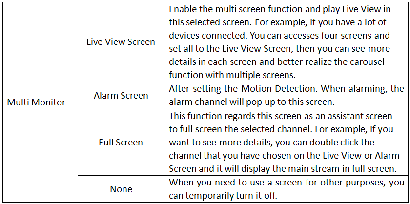
When your PC accesses multiple screens simultaneously, you can choose the appropriate mode as needed. There are four more options for you to choose.
When your PC accesses four screens simultaneously, it will be shown as below:
Chapter II Operations and Settings
Step 1: Add additional displayers to the PC. Click this icon to enter the configuration shown as below.
Step 2: Then the window will pop up:
Step 3: There are four more options for you to choose.
2.1 Live View Screen
If you have a lot of devices connected, you can play the Live View with multiple screens and get a more intuitive visual experience.
If you choose the second screen as the Live View Screen, the second screen will show the display:
Left click your interested channel, it will quickly display the Live View of this channel.
You can select the different Layouts View to see more channels.
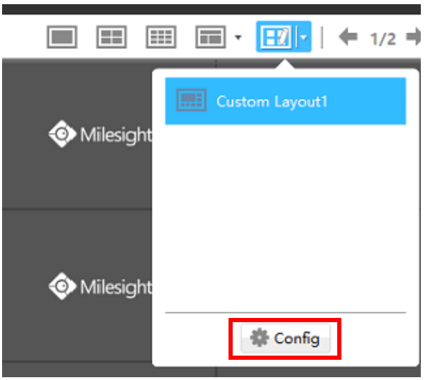
you can also select the customized layouts View which configured in the Main CMS monitor.
When playing Live View, you can right click the mouse. The list is shown follow:
The icons on toolbar in the second Live View Screen are as below:
The description of the icons can be referred to the table below:
The toolbar of the Live View window:
For more details please refer to User Manual of CMS.
2.2 Alarm Screen
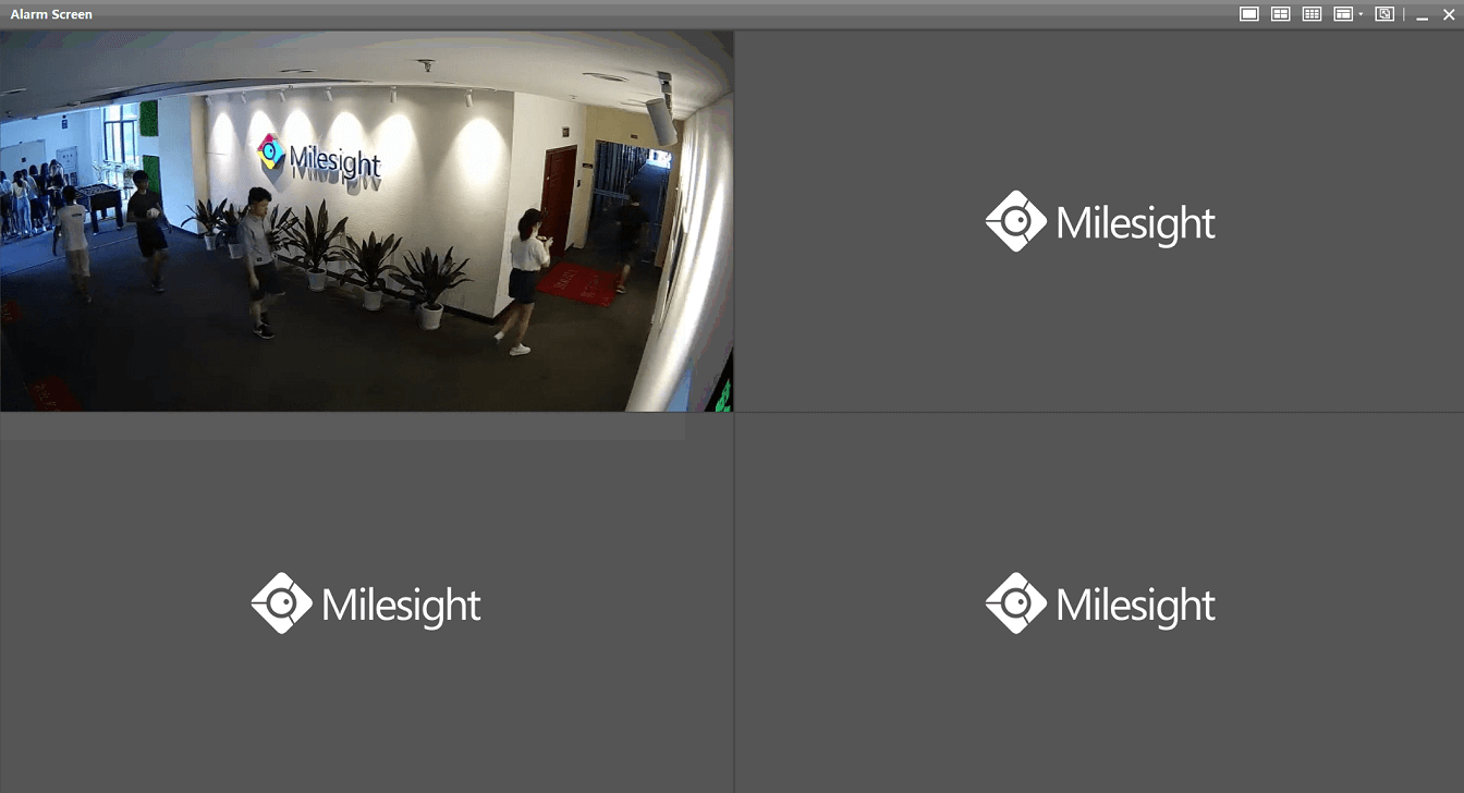
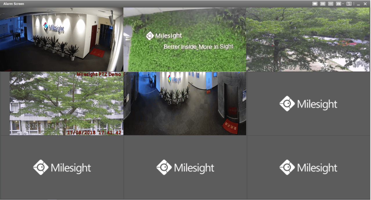
If you choose the screen as the Alarm Screen. When alarming, the alarm channel will pop up to this screen, the screen what you have set up will show the display:
When alarming, the alarm channel will pop up to this screen:
You can select the different Layouts View to see more channels or select the customized layouts View which configured in the Main CMS monitor.
It is worth mentioning that the Alarm Screen features with intelligent adjustment of the number of windows. For example, if you selected the Layout View of four windows and five or more devices trigger the Motion Detection at the same time, the Layout View of the Alarm Screen is automatically converted into nine windows.
When playing Live View, you can play it in full screen mode by right click the mouse and choose the”Show In Full Screen”.
2.3 Full Screen and None
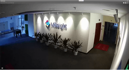
You can also choose the screen as the Full Screen. If you want to see more details, you can double click the channel that you have chosen on the Live View Screen or the Alarm Screen and then it will will display the main stream in full screen.
When you need to use a screen for other purposes, you can choose the screen as None and means that the Live View temporarily turn off.
How to Use NVR P2P on M-Sight Pro
1. P2P
A peer-to-peer (P2P) network is a type of decentralized and distributed network architecture in which individual nodes in the network (called “peers”) act as both suppliers and consumers of resources, in contrast to centralized client–server model where client nodes request access to resources provided by central servers. Networks in which all computers have equal status are called peer-to-peer or P2P networks.
In a peer-to-peer network, tasks (such as searching for files or streaming audio/video) are shared amongst multiple interconnected peers which each make a portion of their resources (such as processing power, disk storage or network bandwidth) directly available to other network participants, with no need for centralized coordination by servers.
With the P2P enabled on NVR, you can add the NVR and view the live video over WLAN remotely without doing any port forwarding on the router.
2. How to Use P2P on M-Sight Pro
You can use P2P function directly after enabling it on the NVR’s web or monitor.
Way 1: Enable on the monitor
Right click on the live view and choose“Menu”->“System”->“Network”->“P2P”, you will see the image as below; Then choose “Enable” and click “Apply” to enable P2P; You can see the P2P state turns to “Activated”, then you can use it freely on “M-Sight Pro”.
If failed to apply this setting, please check these tips:
Way 2: Enable on the web
Enter the web page of NVR ->“Settings”->“System”->“Network”->“P2P”. Details are the same as on the monitor.
If failed to save, please check these tips:
Note:
A. We recommend that you upgrade the firmware version to 7X.7.0.9-r2 or above for better user experience.
B. P2P is a WLAN-required function, so you need to make sure that the network of Default Gateway and Preferred DNS Server are available.
2.3 Settings on M-Sight Pro
Step 1: Open the M-Sight Pro, and click on these icons to add device:
Step 2: Choose “P2P” as “Type”:
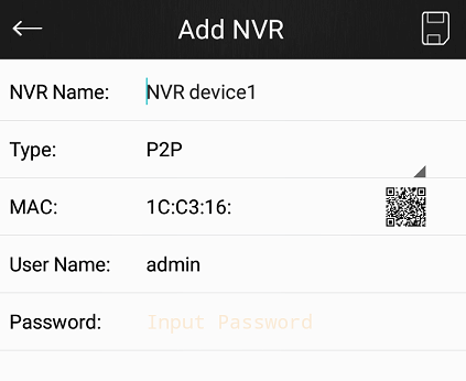
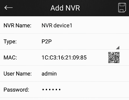
Step 3: Add MAC
There are two ways to add MAC:
Way 1: Input manually after touching area ①;
Way 2: Automatically input by scanning bar code/ QR code after touching icon ②;
Step 4: Input the NVR name, the user name and the password to finish adding device.
2.4 Device management
After adding the NVR via P2P, you can manage it by touching ”Device Manager”. If you want to edit the NVR, touch the icon ①;
If you want to view the live video of your network cameras in the NVR, touch the “Play”;
If you want to delete the NVR, you can slide left on the“Device Name”column and then select“Delete”.
Two Methods to View the Camera from M-Sight Pro
M-Sight Pro is an Milesight Application designed for Milesight camera. There are two methods for us to use M-Sight Pro to view the cameras remotely.
1. Port Mapping
Please do the port mapping as follows:
Step1: Log in router via “winbox” software, enter the IP address, username and password:
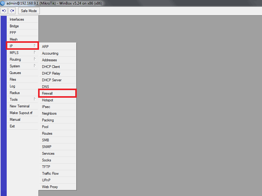
Step2: Click IP→Firewall→NAT
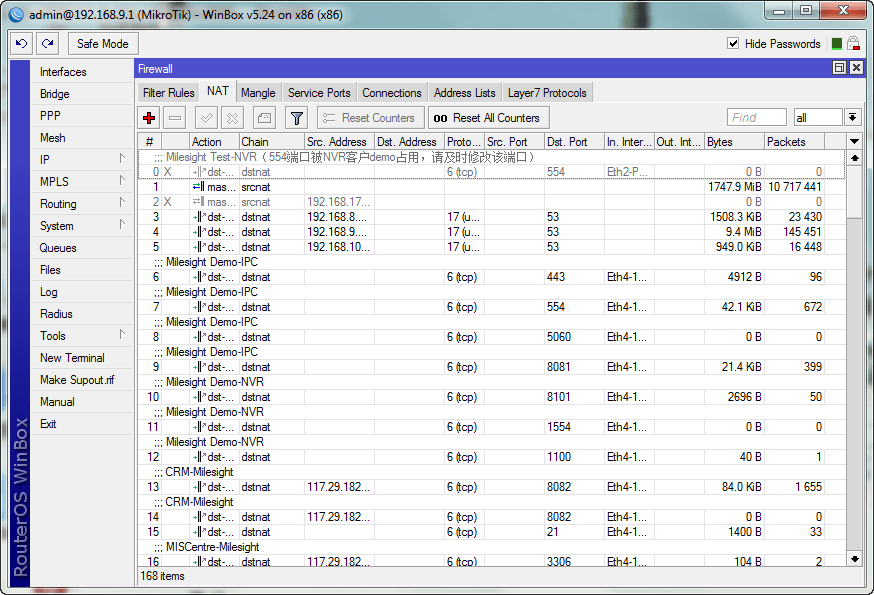
Step3: Click [+], add a new NAT rule, refer the mapping and fill in the info as follows:
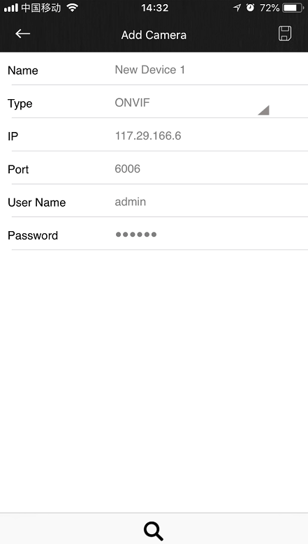
HTTP: 117.29.166.6:6006→ 192.168.8.151:6006
RTSP: 117.29.166.6:5594→ 192.168.8.151:5594
HTTP:
RTSP:
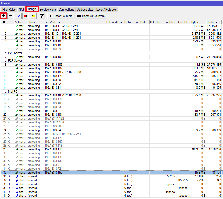
Step4: Click [Mangle]→[+], add a new rule to set the Wan:
Step5: Change the HTTP port and RTSP port via Web:
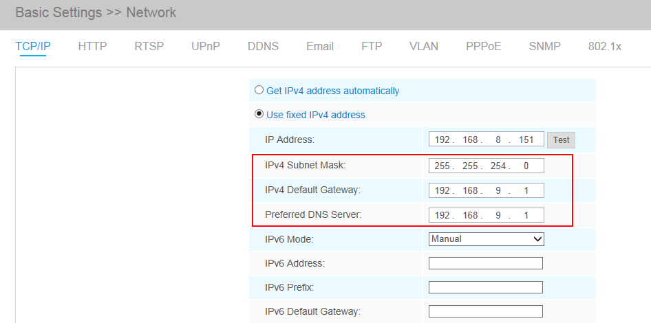
Step6: Change the Subnet Mask, Gateway and DNS:
Step7: There are two ways to visit the camera, Fixed IP or DDNS:
Fixed IP:
Open the App and enter the public IP address to check whether the port mapping is working or not:
DDNS:
If you feel that it is difficult to remember the IP address when visiting the camera, we can link the camera IP address with a domain name, and visit the camera by the domain name. The steps are as follows:
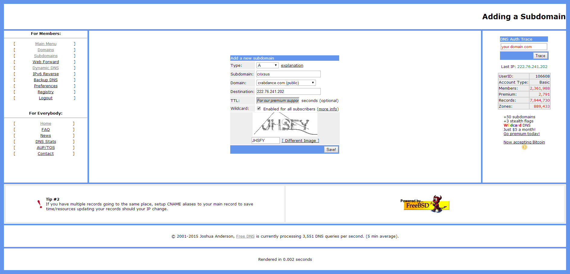
Add a subdomain on the website http://freedns.afraid.org;
Link the domain name with the IP address, 117.29.166.6, which we have mapped before:
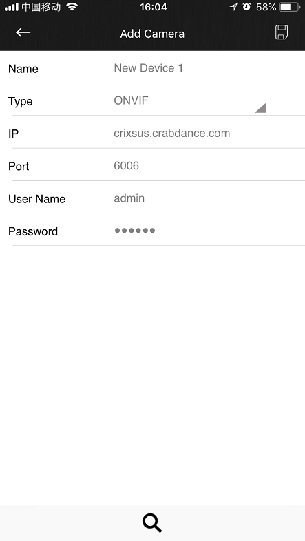
Add the camera to M-Sight Pro by domain name(ONVIF mode);
Or add the camera to M-Sight Pro by domain name(RTSP mode);

2. P2P
Send the MAC address of your camera to us, we will activate your camera. Then M-Sight can visit the camera by the P2P mode.
Please do steps as follows:
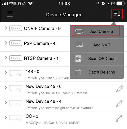
Step1: Click on the top-left button, choose “Device Manager”, click top-right button and choose “Add Camera” to add device. There are three adding types, you should choose to add via “P2P”;
Step2: Enter the MAC address of the camera, the user name and the password. The MAC address of the camera can be generated automatically by scanning the bar code, or you can scan the QR code from web interface. The default user name is: admin, default password is: ms1234;
Step3: Click on the “Save” button to save the device info. After being added successfully, it will get the device number and device name automatically;
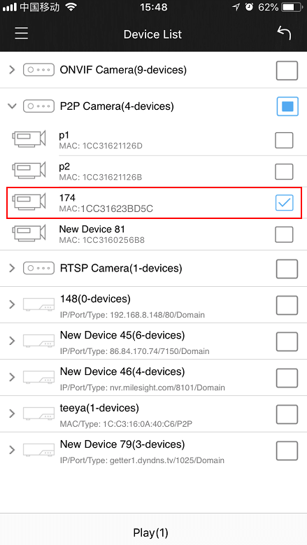
Step4: Play the devices. You have two ways to play live view via P2P;
Choose the devices you want to play in the “Device Manager” interface, and click the devices to play the live view;
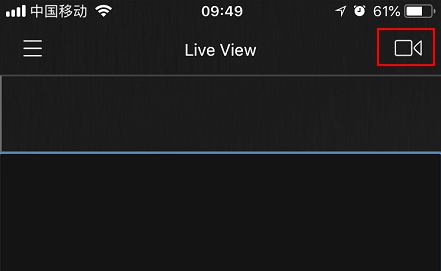
Click on the top-right button in the “Live View” interface, choose the devices you want to play, and click the “Play” button ;
Note:
You can enter the MAC address of the camera as well as scan the bar code/QR code to automatically generate the MAC address.
VMS Enterprise Architecture
Chapter I Introduction
The Milesight VMS Enterprise is featured with Client/Server architecture. The user accesses a system by logging into any server of the system on the client side.

l Server
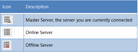
Server refers to Milesight VMS Enterprise Server which are installed on the computer. The initial state of a server is an undefined server. Available on Windows.
A server is responsible for:
-
Communicate with clients and other servers (Only master server)
-
Camera management
-
Get video stream from cameras and forward to client
-
Record video from cameras to local or NAS storage
-
Get event signals and trigger different actions
-
Smart analysis – Store license plate recognition results and black/white list comparison
Recommend: The maximum number of cameras per server is 128.
l System
Icon
A system is made up of one or more servers. Any undefined server needs to be created as a new system or added to an existing system for use.
Multiple servers can form a system which can manage lots of network cameras in different locations. Every server in the same system shares all information about all cameras, users and settings except for recording files.
Recommend:
The maximum number of cameras per system is 2000. The maximum number of servers per system is 25.
l Client
Client refers to Milesight VMS Enterprise Client which are installed on the computer. Available on Windows.
A client is responsible for:
-
Connect to any server, but only to one at a time
-
Camera management, configuration and control
-
View Live videos, up to 4 monitors and 64 channels per monitor
-
Video playback, up to 64 channels synchronously or asynchronously
-
Smart analysis – Black/white list management, ANPR settings and smart search
-
View event notification
-
System and server settings
-
View event logs and audit trail
Note: D3D is required
l User

Every system has a list of user accounts that can have different rights. Only authorized user can access the system. Users are authorized by roles, and there are different types of roles.
Owner: There is only one ‘Owner’ user in the system. It is created when the system is created. It has the highest privileges
Administrator: It owns full access to function and operation permissions, resource access including Camera and Layout
Operator: It can see all cameras and own part access to function and operation permissions in the system
Viewer: It can see all cameras and have view permissions for only partial functions in the system
Custom role: Customize access permission to function, operation and resource including Camera and Layout
Recommend: The maximum number of users per system is 100.
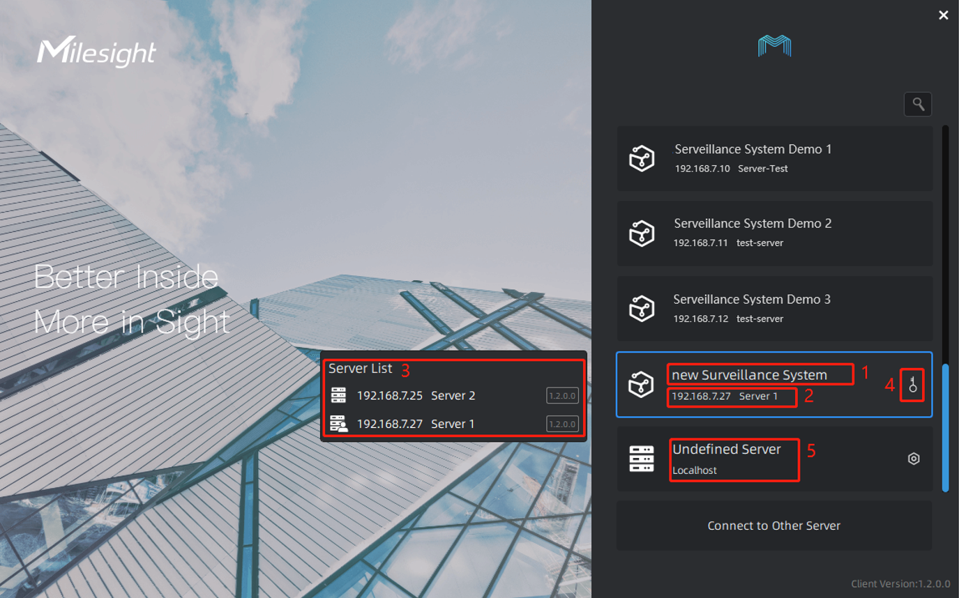
l Login Interface
Interface Description:
Chapter II Operations
2.1 How to add an undefined server into a system
1. Add an undefined server into a new system
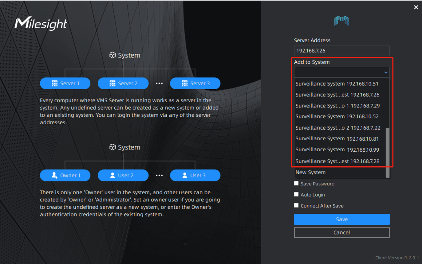
Step 1: Click an undefined server in the login interface. (Undefined servers are shown at the bottom of the list.)
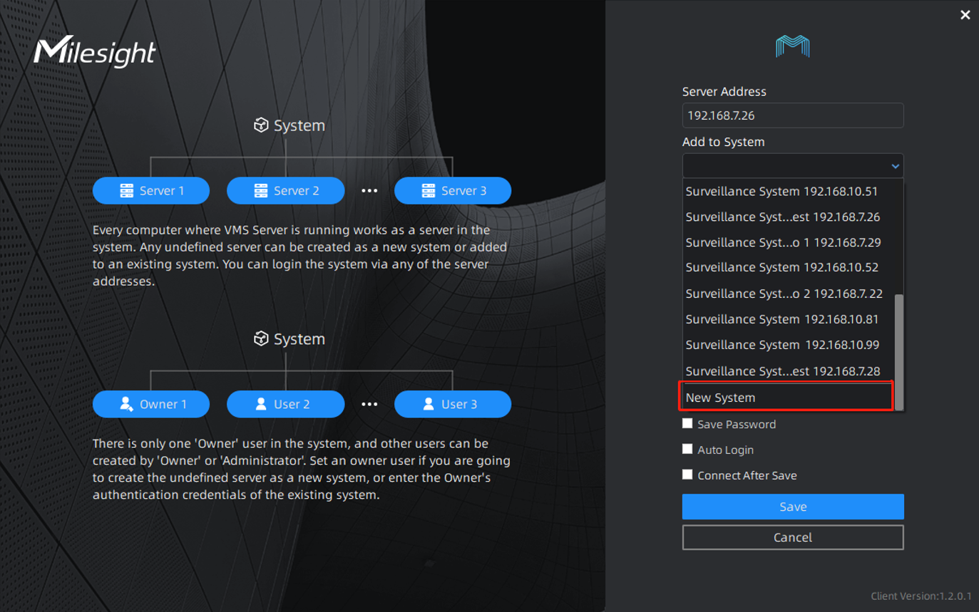
Step 2:Select “New System”to create current server as a new system. (“New System” is shown at the bottom of the selections.)
Step 3:Set the system name, server name and an “Owner” user of the new system, then click “Save”.
You can check “Connect After Save”, then it will log in the system automatically after clicking “Save”.
2. Add an undefined server into an existing system
Step 1:Click an undefined server in the login interface.
Step 2: Select an existing system.
Step 3: Configure server name and enter the owner’s authentication credentials of the system, then click “Save”.
You can check “Connect After Save”, then it will login the system automatically after clicking “Save”.
Note: If the password is entered incorrectly more than 6, the system will be locked for 30 minutes.
2.2 How to detach a server from a system
Step 1:Click “Settings” in the top menu bar. And Click “System & Servers” -> “Server Settings” in the left menu bar. Select the sever in the server list, click “Detach Server”.

Step 2: Click “I Agree”.
If there are multiple servers in the system, you can choose to remove or keep the cameras added to this server.
l Remove cameras of this server from system: after detaching the server from the system, the cameras added to this server will be deleted at the same time.
l Keep cameras of this server in system: after detaching the server from the system, the cameras added to this server will be allocated to other servers of the same system automatically for load balancing.
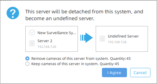
After detaching the server from the system, then it becomes an undefined server.
Note:
1.Only the Owner user has permission to perform the “Detach Server” operation.
2.When a server is offline, if you click “Delete Server”, the server isn’t really detached from the system. It just doesn’t be shown in the server list. Once the server restores online, it still can be displayed in the server list and start working.
If a server has been added into a system, it needs to be detached from the system as an undefined server, then add the undefined server into other system.
How to Use VMS Enterprise Video Wall
Chapter I Introduction
“Milesight VMS Enterprise” supports Video Wall function, which is a necessary advanced function for professional VMS. The Video Wall function supports custom screen combinations and split. It can divide a single monitor into multiple screens, which can be divided into up to 4 screens, or combine multiple monitors into one screen. It controls the maximum number of screens that can be run with a license. If the number of screens connected to the client computer is large enough, more screens can be generated. Moreover, the screens generated by the Video Wall are independent of each other. In particular, the Video Wall function can push the computer desktop to the wall.
Here are some professional terms related to Video Wall, so that you can better understand the function.
-
Monitor
Refers to the monitors actually connected to the client computer.
-
Screen
Refers to the areas created based on monitor for displaying video.
-
Video Wall
It’s made up of screens.
-
Matrix
It is composed of the contents and layout displayed on the Video Wall screen.
Chapter II Operations
2.1 How to Set Video Wall?
Note:
① Make sure that there is a license for Video Wall in the system, and the license quantity is sufficient.
② Make sure the Video Walll Server is installed and running on the Client you want to connect to.
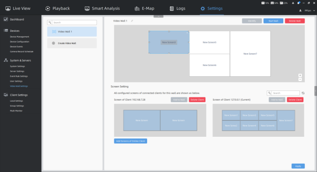
Step1: First, click the button [Creat Video Wall] to create the Video Wall in the Settings -> System & Servers -> Video Wall Settings interface.

Then you can click  to rename the Video Wall.
Step2: Click the button  to pop up the Add Screens window, and all Clients in the LAN will be displayed in the list. You can refresh the list and search the Client.
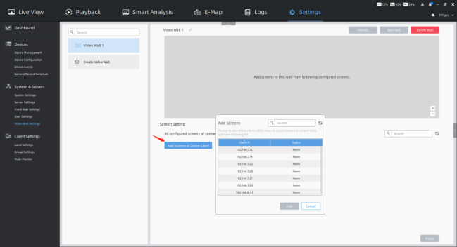
Step3: Then select the Client whose screen does not exist in the current Video Wall in the LAN from the list, and click the button . You can also add multiple Online Clients as needed. Then these added Clients will be displayed in the Screen Setting list. And all monitors actually connected to these Clients will be displayed on the Clients.
You can refresh the Screen Setting list and search for the added Clients. If you want to delete the Client, you can click the button .
.
Step4: Click on a blank area of a monitor on the Client to create a new screen, then you can click and drag the screen to adjust the position. And the screen selected box has 8 small squares that you can drag to adjust the screen size. Each monitor can be divided into up to 4 screens.
In addition, you can click the screen and then click the screen name to rename it, and delete the screen by clicking the icon  in the upper right corner of the screen.
Step5: Click the screen you want, and then click the button  to add the screen to the Video Wall. You can add multiple screens as needed.
You can click and drag any screen on the Video Wall to adjust the position, and drag the small squares of the selected box to adjust the screen size. Click the icon  to delete the screen on the Wall. And you can also adjust the layout of the Video Wall by clicking the icons
  or sliding the mouse wheel.
Step6: Click the button  to apply the settings.
Step7: Then click the button  to run the Video Wall. And then you can use Video Wall function in the Live View interface.
When the Video Wall is running, you can still click and drag any screen on the Video Wall to adjust the screen position and size, which is convenient to match the actual physical position composition of each screen.
In addition, click the button  to identify the corresponding screens. And you can click the button
 to stop running the Video Wall. Or click the button
  to delete the Video Wall.
2.2 How to Use Video Wall?
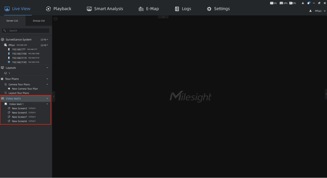
The Video Wall list created in the Video Wall Settings is displayed in the left Resource panel of the Live View. And you can use all screens in the local area network.
Note:
The icon  indicates that the screen is not available, you need to check if the Video Wall Server is running normally.
2.2.1 How to Run Video Wall?
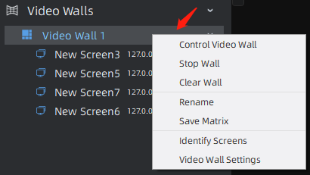
Step1: Right-click the Video Wall and a menu window will pop up as below:
[Control Video Wall]: Pop up the Video Wall control window to use the Video Wall.
[Start Wall]: Run the Video Wall.
[Rename]: Rename the Video Wall.
[Video Wall Settings]: Jump to the Video Wall Settings page.
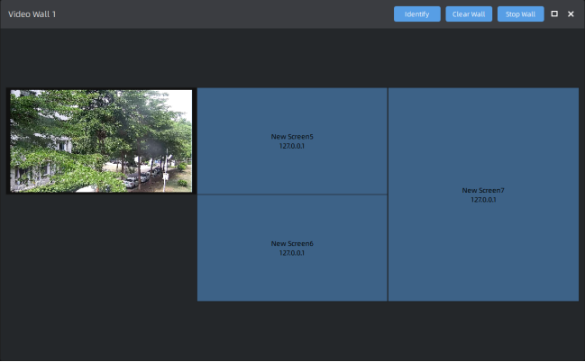
Step2: Select [Control Video Wall] option, and then the following window pops up:
Step3: Click the button  to run the Video Wall. Then you can drag and drop the cameras, layouts and tour plans to the screens.
After running the Video Wall, you can also do the following:
-
l Click the button
 to identify all running screens in the Video Wall.
 -
l Click the button
 to clear the content on all screens in the Video Wall.
 -
l Click the button
 to stop running the Video Wall.
In addition, you can double-click the screen to enter the specific screen. And you can also right-click the screen to do something. For more details, please refer to How to Run Screen?.
Step4: When the Video Wall is running, you can right-click the Video Wall and a menu window will pop up as below:
[Control Video Wall]: Pop up the Video Wall control window to use the Video Wall.
[Stop Wall]: Stop running the Video Wall.
[Clear Wall]: Clear the content on all screens in the Video Wall.
[Rename]: Rename the Video Wall.
[Save Matrix]: Save the content currently playing on each screen of the Video Wall. For more details, please refer to How to Save and Load Matrix?.
[Identify Screens]: Identify all running screens in the Video Wall.
[Video Wall Settings]: Jump to the Video Wall Settings page.
2.2.2 How to Run Screen?
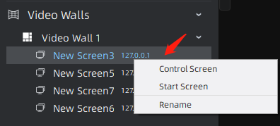
Step1: Right-click the screen and a menu window will pop up as below:
[Control Screen]: Pop up the screen control window to use the screen.
[Start Screen]: Run the screen.
[Rename]: Rename the screen.
Step2: Select [Control Screen] option, and then the following window pops up:
Step3: Click the button  to run the screen. Then you can drag and drop the camera, layout and tour plan to the screen.
After running the screen, you can also do the following:
-
l Click the button
 to refresh the screen.
 -
l Click the button
 to identify the corresponding screen.
 -
l Click the button
 to clear the content on the screen.
 -
l Click the button
 to stop running the screen.
Step4: When the screen is running, you can right-click the screen and a menu window will pop up as below:
[Control Screen]: Pop up the screen control window to use the screen.
[Stop Screen]: Stop running the screen.
[Rename]: Rename the screen.
[Clear Screen]: Clear the content on the screen.
[Identify]: Identify the corresponding screen.
[Push My Desktop]: Push the desktop to the screen for display. If there are multiple desktops, select any one to push as needed.
2.2.3 How to Save and Load Matrix?
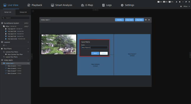
Step1: Right-click the Video Wall and select [Save Matrix] option to save the content currently playing on each screen of the Video Wall. The Save Matrix window will pop up, you can edit the matrix name, and then click the button  .
.
Note:
Make sure the Video Wall is running.
Step2: Then right-click the matrix and a menu window will pop up as below:
[Load to Video Wall]: Each screen will play the content according to the matrix.
[Save]: Save the content currently playing on each screen of the Video Wall to the matrix.
[Rename]: Rename the matrix.
[Set As Default]: Set the matrix as default. Every time you run the Video Wall, each screen will play the content according to the matrix. There is at most one default matrix.
[Delete]: Delete the matrix.
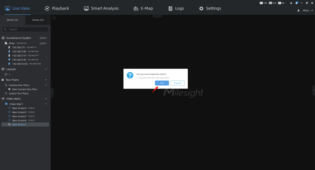
Step3: Select [Load to Video Wall] option, and then the following window pops up:
Click the button  , and then each screen will play the content according to the matrix.
How to Use Record and Playback in VMS Enterprise
1. Introduction
For a VMS software, Live View, Record and Playback must be the three most important functions. Milesight VMS Enterprise has powerful video recording and playback, which are the critical parts of the forensic process. This document will introduce how to configure and use these two functions in order to solve some doubts and problems in use.
2. Disk Settings
Ensure that one or more of the server’s disks are enabled and have space left before configuring record. In addition to local disks, NAS external storage is also supported.
Select Settings→System&Servers→Server Settings→Storage Management and enable one or more disks to save record. It is recommended that the hard disk is used for storing recordings only. Move the mouse to the capacity bar to display more capacity information of the disk.
3. Continuous Recording
3.1 Enable Continuous Record
Step1 Select Settings→Devices→Camera Record Schedule→Schedule;
Step2 Click Server List or Group List to show devices from different servers or groups. Click one camera to configure this channel’s record.
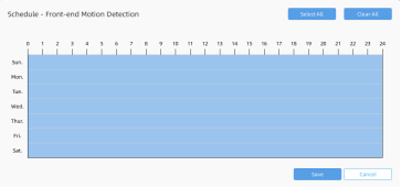
Step3 By default, the time bars in the schedule have been all selected. Click Select All or Clear All to quickly choose or clear all times. When the time bar is blank, you can select a time period by crossing over it. Click one time period and then you can modify its specific time. Click  to copy one day’s schedule to others’.
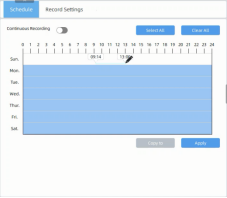
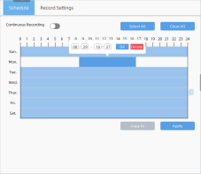

Step4 Enable Continuous Recording  and do not forget to Click Apply to save.
3.2 Continuous Record Settings
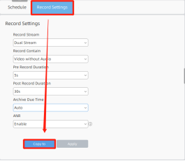
Step1 Select Settings→Devices→Camera Record Schedule→Record Settings;
Step2 Click Server List or Group List to show devices from different servers or groups. Click one camera to configure this channel’s record.
Step3 Configure specific settings of the camera after continuous recording is enabled.
Table1 Description of the settings
Parameters |
Function Introduction |
Record Stream |
Set record stream as primary, secondary or both of them |
Record Contain |
Select whether the record includes audio or not |
Pre Record Duration |
Set the duration of pre-recording from 1s to 10s |
Post Record Duration |
Set the duration of post-recording from 10s to 60s |
Archive Minimum Retention Time |
Set minimum time for recording to expire: Auto(delete the oldest recordings based on the disk capacity); Preset times; Custom time from 1 to 365 days |
Archive Maximum Retention Time |
Set maximum time for the recording to expire: Auto(delete the oldest recordings based on the disk capacity); Preset times; Custom time from 1 to 365 days |
ANR |
Set whether to enable ANR which needs a SD card inserted in Milesight camera added via MSSP |
3.3 Copy Record Schedule and Settings
Both Schedule and Record Settings support copy one channel’s to others’. We take Record Settings as an example.
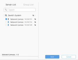
Step1 Click Copy to and then check the cameras you want to copy the configuration to.
Step2 You can also see all cameras from different Servers or Groups by selecting Server List or Group List.
Step3 Click Save and you will find the checked cameras’ configuration is the same as the first one.
4. Event Record
Event Record of VMS Enterprise is based on Event Rules. So you need to set it in Event Rule Settings interface.
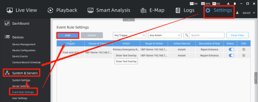
Step1 Select Settings→System&Servers→Event Rule Settings and click Add to set a new rule;
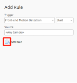
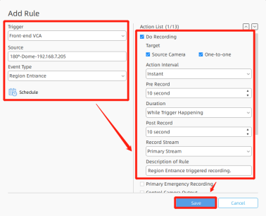
Step2 Select the event which you want to trigger the recording. We take Region Entrance in Front-end VCA as an example. Then click <Any Camera> and all cameras will show up in Server List or Group List. Check one or more cameras as the source and click save.
Step3 Click  to bring up the window of schedule. The way to configure it is just the same as it in Continuous Recording. Don’t forget to click Save.
Step4 Check Do Recording or Primary Emergency Recording in Action List. Primary Emergency Recording is based on recording schedule, which should be configured first at Camera Recording Schedule. Trigger primary stream recording when event occurs.
Table2 Description of the settings
Parameters |
Function Introduction |
Do Recording |
Primary Emergency Recording |
Target |
Set which camera to record: Source Camera(One-to-one means that event from a particular camera triggers recordings of not all source cameras but only this camera when there are more than one source cameras); Custom selected cameras |
√ |
√ |
Action Interval |
Set time interval between two Actions: Instant; 5s; 10s; Custom time from 1 to 3600s |
√ |
√ |
Pre Record |
Set the duration of pre-recording from 0s to 10s |
√ |
× |
Duration |
Set the duration of whole action: While Trigger Happening; Custom time from 1 to 3600s |
√ |
√ |
Post Record |
Set the duration of post-recording from 0s to 120s |
√ |
× |
Record Stream |
Set record stream as primary or secondary stream |
√ |
× |
Description of Rule |
A brief description as needed for easily finding this rule |
√ |
√ |
Step5 Configure the event record rule as needed and click Save.
Step6 Click Apply to save the rule changes.
Take the following figure as an example, when Panoramic Dome Camera detects Region Entrance, it will trigger recording its video. Don’t forget to click Apply in Event Rule Settings interface.
Note: All front-end triggers should be enabled on Milesight camera side first. You can configure it in Device Events module.
5. Basic Playback

Click Playback on the top. And then the playback interface will show up. Choose and double click a channel from Server List or Group List to replay your recordings. The icon  means this channel has recordings to play.
(1) Toolbar on the top
Move your mouse to the video, and then the toolbar will show on the top.
Click  to turn on Speaker, and you can adjust the volume of the speaker from 1~100. This item is available only for cameras which support built-in mic or Audio I/O.
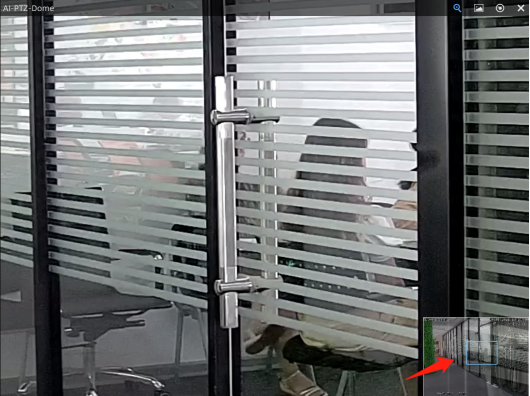
Click  to enable digital zoom. A thumbnail of the enlarged position is displayed in the lower right corner. Mouse dragging and wheel scrolling to move and zoom in/out.
Click  to take a snapshot. The blue text will lead you to the snapshot storage path.
Click  to open the Fisheye toolbox. Here are a list for each icon of Fisheye toolbox.
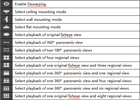
Click  to close this channel’s playback.
(2) Right-Click Menu
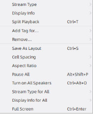
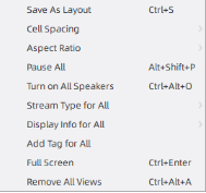
Right click the video and the menu will show up.
The meanings of the items on the right-click menu can be referred to the table below:
Item |
Description |
Stream Type |
Auto, Primary and Secondary supported. Auto means the playback video will automatically switch stream according to computer performance. |
Display Info |
Choose to display stream information at Left or Right, or customize the position of info. You can also hide the stream information. |
Split Playback |
Divide the video files into several channels during specified time period. Users can watch playback videos of different time periods simultaneously. |
Add Tag for |
Add tag for the selected cameras or all cameras in the playback panel. |
Remove |
Choose Selected Views or All Views in Layout to remove the camera playback. |
Save As Layout |
Click it to save the current layout to Layouts list. |
Cell Spacing |
Set the cell spacing size among the live view windows in the layout. There are four options available, including None, Small, Normal and Large. |
Aspect Ratio |
Choose 1:1, 4:3, 16:9, 3:4 and 9:16 to show the window aspect ratio. |
Pause/Resume all |
Pause/Resume all playback in the current layout. |
Turn on/Mute All Speakers |
Enable or disable the speakers of all cameras in the current layout. |
Stream Type for All |
Set stream type for all cameras in the current layout. |
Display Info for All |
Set to display stream information of all channels in the current layout. |
Full Screen |
You can choose Layout to display all cameras in the layout to full screen. Click again the Exit Full Screen to restore the normal window. |
Right click on a position in the layout where there is no video and the menu will change into:
There are two more items:
Add Tag for All |
Add tag for all cameras in the playback panel. |
Remove All Views |
Remove all cameras’ playback from this layout. |
(3) Playback Toolbar
Select a certain channel in the current layout and click  to show the calendar. The blue date and time both indicate availability of recordings. Click the date and time you want to locate to.
Click to lock recording file, and you can set locked time duration and notes.
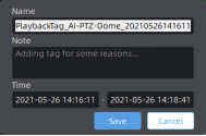
Click  to add tags for selected channels, and you can set tag name, note and time duration.
Click  to show Archive Management which can be used to check and retrieve tag and lock files.

Click  to switch to Asynchronous Playing or Synchronous Playing.
Asynchronous Playing: The timeline only represents the recording of selected channel.
Synchronous Playing: Playback all channels in the current layout synchronously. The thick timeline bar represents recordings of currently selected camera, while the thin bar represents recordings of all channels in the current layout.
Click  /
/ to play previous or next event video.
Click /
/ to play previous or next frame of the recording.
Click /
/ to adjust the playback speed to 1/32, 1/16, 1/8, 1/4, 1/2, 1X, 2X, 4X, 8X, 16X or 32X.
Click /
/ /
/ to rewind, play or pause the video.
Click to move the current playback time to the center of timeline bar. The short white vertical line which represents the position of the current playback moment will move to the centre of the time bar.
Drag to zoom in/out timeline bar. Or you can just scroll the mouse wheel on timeline bar to do so.
(4) Right-Click Timeline Bar
Right-Click the timeline bar and hold down to drag to move the time bar sideways.
Right-Click the timeline bar, the menu will show up as follows. If there has been a part of video selected and it contains locked video and tags, right-click menu will have more items.
The meanings of the items on the right-click menu can be referred to the table below:
Item |
Description |
Start Selection/End Selection |
Select start/end time of period on the timeline. |
Clear Selection |
Clear selection on the timeline. |
Zoom to Selection |
Extend the selected period to whole timeline. |
Add Tag |
Add tag for the selected period. |
Lock File |
Lock the selected period. |
Split Playback |
More Details in 6.2 Split Playback |
Export Video |
Export the selected period. |
Unlock File |
Unlock the locked video file. |
Edit Tag |
Edit tag which you set. |
Export Tag |
Export tag which you set. |
Play Tag Video |
Play videos with tag you set. |
Delete Tag |
Delete tag which you set. |
Show Thumbnails |
Show thumbnail of the corresponding time. Users can also resize the thumbnail timeline as needed. |
Show Tags |
After setting the tags, you can choose the option to show the tag on the timeline
|
Show Locks |
After setting the lock files, you can choose the option to show the lock file on the timeline |
(5) Tags for Playback
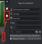
Click the Hide/Show bottom to pop-up right side menu and click the tag icon to show Tags for Playback.
Select which channels to search tags from.
Select which types of tags to search.
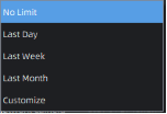
Select the time duration for searching tags
Search keyword of tags’ names and notes. Refresh the tag list and chose how to sort the tag list (Tag Start Time, Tag Name, Camera Name and Create Time).
Double click the tag you want, and the video of the corresponding channel then jumps to the time of the tag and flashes the window.

6. Event and Split Playback
(1) Event Playback
If the channel is configured with rule-triggered recording, the timeline bar of Playback will have different colors representing different events.
Click Show Event Mask to check event type to be shown on the timeline, the timeline will show different colors according to selected event type as below:
Click the  button to enter Event Mask Colors Setting interface, it supports customizing different colors for different events according to the user’s requirement.
Click Event Only to exclude continuous recording.
(2) Split Playback
Split Playback allows you to divide a period time of recording into several parts when watching playback, so that users can watch videos of different time simultaneously.
Split Playback setting steps are as below:
Step1: Right click the playback window of a channel and click Split Playback, or right-click the selected time period on the timeline and choose Split Playback, and a window will pop up.

Time Period setting
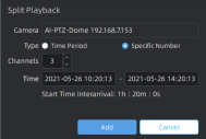
Specific Number setting
Step2: Check a type to split the video file. If you choose the Time Period, and set Time Interval and Start/End Time, then the channels will be split automatically by VMS system as above. If you choose the Specific Number, and set channel number and Start/End Time, then Time Interval will be calculated and split automatically by VMS system as above.
Step3: After setting, click , and the selected video will be split to new channels to replay asynchronously on the playback layout as shown below:
How to Set VMS Enterprise Event Rules
Ⅰ. Introduction
Event rules are used to associate events and actions. Milesight VMS Enterprise supports rich events, multiple actions and alarm modes, which you can combine freely and configure as your need. Every event can be set to trigger many kinds of actions at the same time. Also, every event can be set to trigger different actions in different time periods. After configuring the event rules, when an event is detected, it can promptly remind or automatically trigger actions according to your settings. In this case, focusing on events becomes easier and you won’t miss the events you care about.
By default, some rules have been automatically created for you in the system. These rules are used to notify the abnormalities that may occur in the system. If an event is detected, you will receive a notification in the Notifications panel. It is strongly recommended to keep them. You can also adjust them as needed.
Ⅱ. How to set an event rule
If you’re not an owner or administration, make sure you have permission for event rule settings.
2.1 Add an event rule
Step 1: Click “Settings” -> “System & Servers” -> “ Event Rule Settings”.
Step 2: Click “Add”, set trigger, schedule and action, then click “Save”.
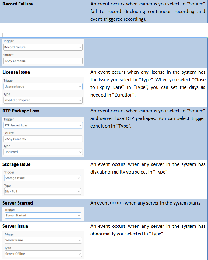
There are many kinds of events and actions. Different events or actions have corresponding settings. Here you can check the below table to know more about them.
-
Trigger
-
Action
Note:
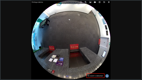
When an event is detected, if you want the corresponding camera in live view interface to be prompted with a flashing box, only need to check “Show Flashing Border” in “Settings” -> “Client Settings” -> “Local Settings” -> “Alarm”.
Each event can trigger different actions. If the checkbox of action is disabled, the event doesn’t support triggering this action.
Step 3: After adding event rules, you can see them in the list.
Optional: You can also edit or delete the event rules as needed.
Step 4:
After completing all operations, click “Apply”.“*” means the rules haven’t been saved, don’t forget to click “Apply”.
Ⅲ. Example
-
Setting
Set the following event rules in the system.
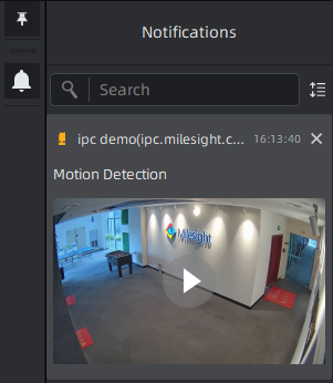
①. From 1 p.m to 4 p.m, when a motion event is detected in “ipc demo”, call “ptz demo” preset and show a notification.
②. From 4 p.m to 6 p.m, when a motion event is detected in “ipc demo”, do recording, show notification and email to user “Test”.
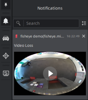
③. When any camera in the system has video loss, show a notification.
④. When any camera in the system fails to record, show a notification.
⑤. When any user login the system, show a notification.
⑥. Add an icon to each camera. After clicking the icon, show text in live view of the camera and push the live view of the camera to display on full screen.
-
Result
①. From 1 p.m to 4 p.m, when a motion event is detected in “ipc demo”, call “ptz demo” preset and a notification will be shown in Notifications panel.
②. From 4 p.m to 6 p.m, when a motion event is detected in “ipc demo”, a notification will be shown in Notifications panel. User “Test” will receive an email. And you can view the recording in Playback interface.
③. When a camera in the system has video loss, a notification will be shown in Notifications panel.
④. When a camera in the system fails to record, a notification will be shown in Notifications panel.
⑤. When a user login the system, a notification will be shown in Notifications panel.
⑥. After clicking the icon, text will be shown in the live view of the camera.
All events will be recorded, you can view them in Logs interface.
How to Enable VMS Enterprise Multi-Monitor
Chapter I Introduction
“Milesight VMS Client” supports multiple monitors display setting, which supports up to 4 monitors. Multi-Monitor function meets the needs of users for more application scenarios. Each monitor has 4 modes to choose from, including [None], [Live Screen], [Alarm Screen] and [Full Screen]. Both Live Screen and Alarm Screen support up to 64 channels in single screen. The Full Screen only supports displaying 1 channel. In addition, Multi-Monitor function also supports identifying monitors of corresponding screens.
Different screen modes support different functions.
l None:
No settings are made for other monitors.
l Live Screen:
For this mode, you can add any camera you want to display on the specified monitor so that you can view the real-time video. In addition, the Live Screen mode supports up to 4 monitors and 64 live view channels per monitor.
l Alarm Screen:
For this mode, you need to set the event rules and select the action of [Show on Alarm Screen] for the camera, then the real-time video will be played on the specified monitor when the corresponding event is triggered. This is helpful for users to track camera event in time and view the real-time video.
l Full Screen:
For this mode, you can directly set [Show on Full Screen] for the selected camera in the Live View interface, then the real-time video will be showed on the specified monitor as full screen mode. Of course, you can also set the event rules and select the action of [Show on Full Screen] for the camera, then the real-time video will be played on the specified monitor when the corresponding event is triggered. It solves the inconvenience of not being able to operate other interfaces after the Live View interface channel goes full screen.
l E-Map:
Users can use the E-map function in this mode.
l Playback:
For this mode, users can search and play back the recorded files of selected cameras.
Note: You can only set one Alarm Screen and one full screen, and there is no limit to the number of Live Screen, E-Map Screen and Playback Screen.
Chapter II Operations
2.1 How to Enable Multi-Monitor?
First, click the Enable icon to enable Multi-Monitor and then click [Apply] button to apply Multi-Monitor in the Settings -> Client Settings -> Multi-Monitor interface.
Note:
l This page can only display configuration items of four monitors, even if you have more than four monitors.
l There is no configuration quantity limit for Live Screen, but Alarm Screen and Full Screen can only set one separately.
In addition, you can click [Identify] button to see the corresponding number of each available monitor.
2.1.1 How to Set [None] Mode?
If you don’t want to make any settings with the specified monitor, you can select [None] option and then click [Apply] button to apply [None] Mode.
2.1.2 How to Set [Live Screen] Mode?
Step 1: Select [Live Screen] option for the specified monitor and then click [Apply] button to apply [Live Screen] Mode.
Step 2: Drag the camera which you want to show on the specified monitor from the list on the left and move it into the Live View window, then you can view the real-time video on the specified monitor.
Step 3: If you want to close Live Screen, you can move the mouse to the top of the screen to display the top bar, then you can click the icon  and select [Close] button to close it. After the screen is turned off, the monitor will automatically change to [None] Mode. If you want to use Live Screen again, you need to reset [Live Screen] Mode.
2.1.3 How to Set [Alarm Screen] Mode?
Step 1: Select [Alarm Screen] option for the specified monitor and then click [Apply] button to apply [Alarm Screen] Mode.
Step 2: Click [Add] button to add the event rule in the Settings -> System & Servers -> Event Rule Settings interface, then set the trigger type, the source of trigger and schedule you want, and set the action of [Show on Alarm Screen]. After setting the event rule, click [Save] button.
Note:
The following trigger types support the action of [Show on Alarm Screen]:
Front-end Motion Detection, Front-end Audio Alarm, Front-end External Input Alarm, Front-end VCA, ANPR, Record Failure, RTP Packet Loss and Client Trigger.
Step 3: Then the event rule will be added to the event rule list. Click [Apply] button to apply the customized event rule.
Step 4: When the camera is triggered, the real-time video will be played on the specified monitor.
(Note: The picture on the left is Monitor1 and the picture on the right is Monitor2.)
Step 5: If you want to close Alarm Screen, you can refer to Step 3 of 2.1.2 for operation steps.
2.1.4 How to Set [Full Screen] Mode?
Step 1: Select [Full Screen] option for the specified monitor and then click [Apply] button to apply [Full Screen] Mode.
Step 2: Right-click the Live View window for the selected camera, and set Multi-Monitor as [Show on Full Screen] option. Then the Live View window of the camera will be displayed on the specified monitor as Full Screen.
(Note: The picture on the left is Monitor1 and the picture on the right is Monitor2.)
In addition, you can also set the event rule and select the action of [Show on Full Screen] to trigger [Full Screen] Mode. Please refer to Step 2 and Step 3 of 2.1.3 for operation steps.
Step 3: If you want to close Full Screen, you can refer to Step 3 of 2.1.2 for operation steps.
2.1.5 How to Set [E-Map] Mode?
Step 1: Select [E-Map] option for the specified monitor and then click [Apply] button to apply [E-Map] Mode.
Step 2: The E-Map interface will display on the selected screen. Click ”Create” button
to create a new map.
Step 3: You can drag the camera onto the map and make some further settings.
2.1.6 How to Set [Playback] Mode?
Step 1: Select [Playback] option for the specified monitor and then click [Apply] button to apply [Playback] Mode.
Step 2: The Playback interface will display on the selected screen. You can search and play back the recorded files of selected cameras.
Step 3: If you want to close Playback Screen, you can move the mouse to the top of the screen to display the top bar, then you can click the icon and select [Close] button to close it. After the screen is turned off, the monitor will automatically change to [None] Mode. If you want to use Playback Screen again, you need to reset [Playback] Mode.
How to Set VMS Enterprise Paging & Layouts & Tour Plans & Instant Playback
Chapter I Introduction
Live View is mainly used for viewing real-time video. The interface is mainly made up of left Resource Panel, center Viewing Panel and right Function Panel.
The left Resource Panel displays all servers and cameras in the VMS system. The center Viewing Panel supports up to 64 individual live camera streams on a single page. The right Function Panel has four tabs, including Notifications, ANPR Preview, PTZ Control and Tour List.
Here we focus on the Paging, Layouts, Tour Plans and Instant Playback function in the Live View interface.
1.1 Paging
Live View supports paging function. A single page can play up to 64 channels. Users can select the number of channels to play on a single page according to their needs.
1.2 Layouts
Both Live View and Playback support layouts. Layouts can be customized, so you can save the currently playing channels and their locations, which helps you watch and manage Live View and Playback more efficiently. In addition, users of Administrator or Owner role can share all layouts within the system with Operator or Viewer or the customized roles, so that users in Operator or Viewer or the customized roles can use the layouts and access the devices in the layouts.
1.3 Tour Plans
Live View supports Tour Plans, including Camera Tour Plans and Layout Tour Plans. All channels currently playing or the layouts will automatically switch Live View window by using the function, which makes it easy for users to view the live view by auto-switching.
1.4 Instant Playback
Live View supports Instant Playback function for the channel with video recording. Users can quickly view the video file in the last 5 minutes. In addition, when Instant Playback is enabled, it supports integrated window functions, including Digital Zoom, Fisheye Setting, Snapshot, Recording and so on.
Chapter II Operations
2.1 Paging
2.1.1 How to Set Paging?
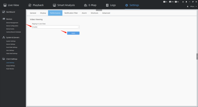
Step 1: Enable “Paging in Live View” in the Settings -> Client Settings -> Local Settings -> Performance interface, and then click [Apply] button.
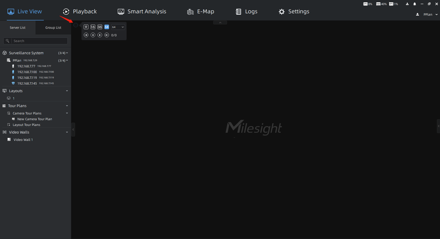
Step 2: Then the icon  will be displayed in the upper left corner of the center Viewing Panel, and click it to pop up the page controller.
Step 3: In the page controller you can set the number of channels to play on a single page, and you can click to jump to the first page/last page/previous page/next page.
2.2 Layouts
2.2.1 How to Set Customized Layout?
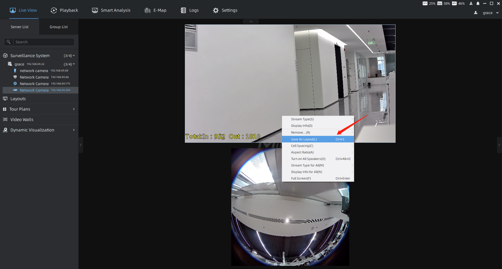
Step 1: First, determine the channels and their locations you’re interested in, then right-click the camera live view window in the Live View interface to pop up a menu. And select [Save As Layout] option to save the layout.
Step 2: You can name the new layout, and click [Save] button to save it. Then the layout will be displayed under the Layouts module in the left Resource Panel.
Step 3: Right-click the corresponding layout and select [Play] option to preview the camera in the layout. You can also directly double-click the corresponding layout for quick viewing.
Note:
The operation of setting layout in the Playback interface is the same as that in the Live View interface.
2.2.2 How to Share Customized Layout?
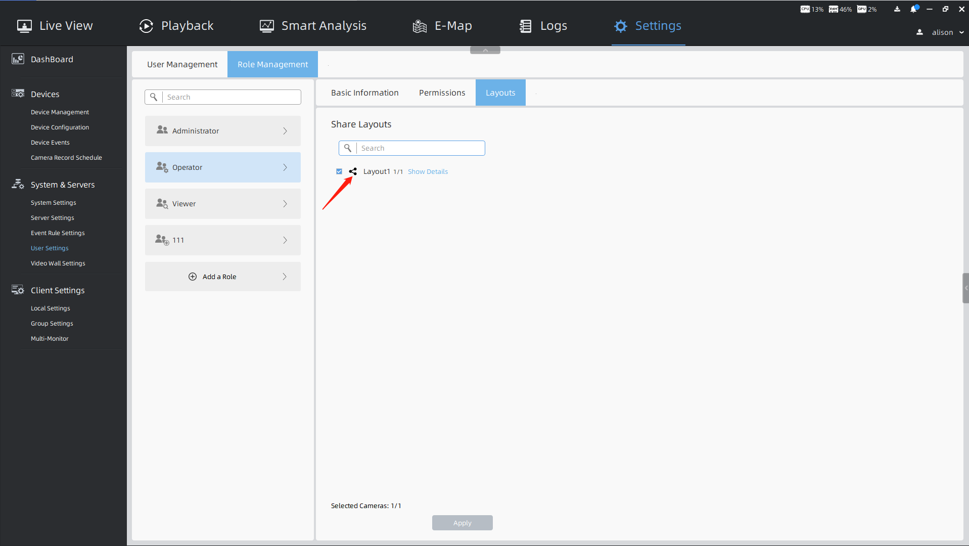
Step 1: In the Settings -> System & Servers -> User Settings -> Role Management interface, users of Administrator or Owner role can select the corresponding role to share the layout.
Step 2: Then check the layout you want to share on the Layouts page, and then click [Apply] button, the layout icon  will change to
 . In this way, all users under the corresponding role can use the layout and have access to the devices in the layout.
Step 3: You can click [Show Details] button to check devices in the layout. Hover your mouse over the channel to see the thumbnail and related information.
2.3 Tour Plans
The operations of Camera Tour and Layout Tour are similar. Here we take the operations of Camera Tour as an example.
2.3.1 How to Start and Configure Tour?
Step 1: There are three ways to start Camera Tour.
Method 1: Determine the channels you’re interested in, and right-click the camera live view window in the Live View interface to pop up a menu. And select [Start Tour] option to configure tour.
Method 2: Multiple cameras in the list can be selected by holding down [Ctrl] key on the keyboard, then right-click on the list to pop up a menu. And select [Start Tour] option to configure tour.
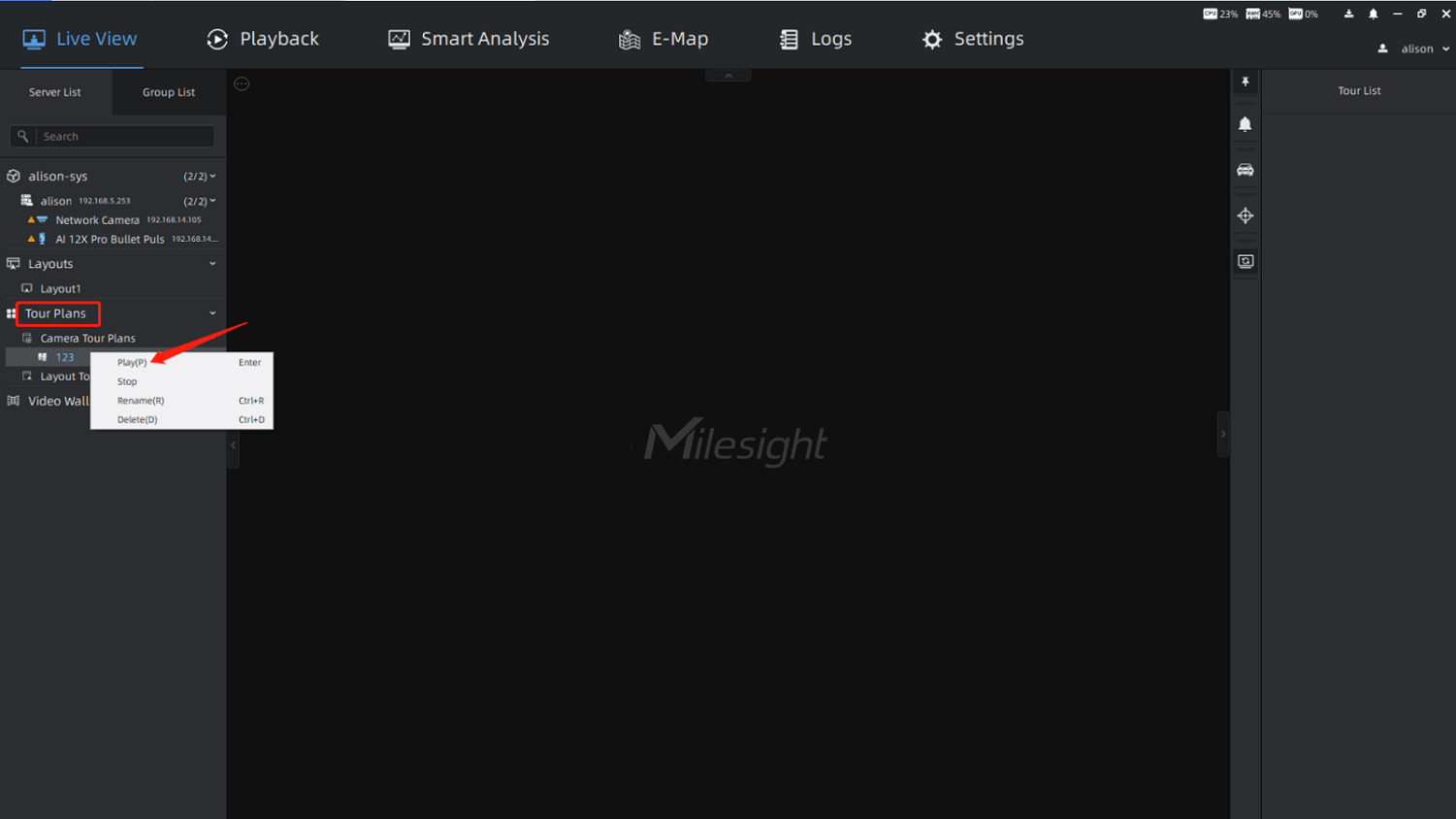
Method 3: If you already have a saved tour plan, you can right-click the corresponding tour under the Tour Plans module in the left Resource Panel, and select [Play] option to start tour. You can also directly double-click the corresponding tour to start tour quickly.
Step 2: After starting tour, you will enter the Tour Config interface. Then you can edit the name, the number of channels per play and tour interval. And click [Play] or [Save and Play] button to enter the real-time Tour interface. The saved tour will be displayed under the Tour Plans module in the left Resource Panel.
Step 3: Click the Tour List icon  , and all channels added to the tour will be displayed in the right panel. The icon
  indicates that the channel is currently playing.
Step 4: After clicking the icon  to pause the tour, you can modify the tour name, the number of channels per play, tour interval. You can also drag the camera from the left Resource Panel to the Tour List to add it. And click the icon
  to delete it by moving the mouse over the corresponding channel in the list. After the operation is completed, then click the icon
  to save the current configuration. You can click the icon
  to stop the tour.
2.4 Instant Playback
2.4.1 How to Enable Instant Playback?
Step 1: For the channel with video recording in the last 5 minutes, you can click the Instant Playback icon  on the top toolbar of video window to view the video.
(Instant Playback is supported for multiple channels at the same time.)
Step 2: When Instant Playback is enabled, it supports the following integrated window functions. And you can use the corresponding function as needed.
① The top toolbar functions of video window:
Turn on Speaker, Start Talking, Enable Digital Zoom, Snapshot, Start Recording, Fisheye Setting, Close.
② The right – click menu function of video window:
Stream Type, Display Info, Add Tag for Selected Cameras or All Cameras in Layout, Full Screen Current View or Current Layout, Start Tour, and so on.
③ The bottom toolbar functions of video window:
Play, Pause, Play in Playback, Control playback progress through timeline.
Note:
Only when the continuous recording schedule is set, Instant Playback can support adding tag.
