The LTS Connect mobile client (Android), is designed for the phone or tablet based on Android 4.1 or later. With the Mobile Client, you can remotely control devices (NVRs, DVRs, network cameras, indoor stations, doorbells, security control panels, the Pyronix devices, the access control devices, etc) via Wi-Fi or cellular network. You can also share your devices to other accounts and use devices shared from other users. The Mobile Client provides access to the PT service, which is a cloud service, to manage your devices.
Note
Network traffic charges may be produced during the use of the Mobile Client. For details, refer to the local ISP.
System Requirement
Android 4.4 or later versions.
Conventions
In the following chapters, we simplify LTS Connect mobile client (Android) as “Mobile Client”, devices such as DVR, NVR, encoder, and network camera as “device”, and devices which support being added to PT Cloud service as “PT Cloud Device”.
Chapter 2 Visitor Mode
Visitor mode allows you to manage devices on the Mobile Client without registration. When you log in as a visitor, a visitor account will be created for you automatically, and the account will not change on the same phone or tablet.
Caution
For information security, please use visitor mode cautiously, which is NOT password-protected.
Note
In visitor mode, you can only manage your devices on a same phone or tablet. To avoid this inconvenience, you can register an account. For details about registering account in visitor mode, see Register an Account in Visitor Mode.
LTS Connect Android User Manual
Read More : LTS Sapphire Password Reset Guide
Most of the functions supported in a registered account are supported in visitor mode. Tap Visitor Mode on the Home page or the Login page to enter visitor mode.
The followings are the functions supported in visitor mode.
Device Management
Add devices to the Mobile Client and configure device settings. See Add Device for Management
and Configure Your Device for details.
Sharing Device
Tap → Scan QR Code to scan the QR code of another visitor account to share device(s) to the account. For details about sharing device, see Device Sharing.
Note
To get the QR code of a visitor account, go to More → Account Management.
Live View and Playback
View live video of the added devices and play back the videos. See Live View and Playback for details.
Access Control
Control door status and check access control events. See Manage Access Control Devices for details.
Note
Make sure you have added access control devices to the Mobile Client.
Alarm Configuration
Configure the alarm notifications on Alarm Notification page. See Notification for details.
Though the visitor mode allows you to manage devices without registration, you can only manage your devices on one phone or tablet. With a registered account, you can manage devices on different phones or tablets.
Steps
Note
See Register by Email Address and Register by Mobile Phone Number for details.
Chapter 3 Registration
You can register an account by your mobile phone number or your email address. With a registered account, you can log in to the Mobile Clients running on different mobile phones or tablets, which provides convenience for managing your devices.
Note
You can use visitor mode to manage your devices without registration. See Visitor Mode for details.
You can register an account by your email address.
Steps
Note
We highly recommend you to create a strong password of your own choosing (using a minimum of 8 characters, including at least three kinds of following categories: upper case letters, lower case letters, numbers, and special characters) in order to increase the security of your product. And we recommend you change your password regularly, especially in the high security system, changing the password monthly or weekly can better protect your product.
You can register an account by your mobile phone number.
Steps
Note
We highly recommend you to create a strong password of your own choosing (using a minimum of 8 characters, including at least three kinds of following categories: upper case letters, lower case letters, numbers, and special characters) in order to increase the security of your product. And we recommend you change your password regularly, especially in the high security system, changing the password monthly or weekly can better protect your product.
Chapter 4 Device Management
You need to add devices to the Mobile Client before you can do further remote operations such as live view and playback.
The devices added to the Mobile Client will be displayed in the device list.
In the device list, the video resources are displayed as the thumbnails of their video channel images; the security control resources, doorbells, and access control resources are displayed as device pictures.
You need to add devices to the Mobile Client first so that subsequent operations such as live view and playback can be available. If you want to receive alarm event information from a device, you should add it by scanning QR code or LTS connect domain.
Note
For details about managing alarm event information, see Notification.
The Mobile Client can detect the online devices in the same local area network with your phone or tablet, and you can add the detected online devices to the Mobile Client.
Before You Start
Make sure the devices are connected to the same local area network with the phone or tablet.
Steps
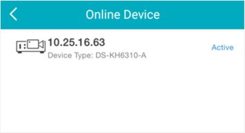
Figure 4-1 Online Device
Note
You can add the device by scanning the device’s QR code. You can also add device(s) by scanning the QR code obtained via the web page of the device.
Steps
Note
to enable the flashlight if the scanning environment is too dark.
Note
Note
You can add the device by fixed IP address or domain name. The streaming speed of devices added by IP/domain is faster than those added by LTS Connect domain.
Before You Start
If you want to add the access control device, activate it before adding. See the user manual of the access control device for details.
Steps
Address
Device IP address or domain name.
Camera No.
The number of the camera(s) under the device can be obtained after the device is successfully added.
Note
Edit Device Information
On the Device Information page, tap to edit the basic information of the device.
Star Live View Tap Start Live View to view the live view of the device.
Delete a Device Tap and then tap Delete to delete the device.
Configure Device Parameters
Tap and then tap Remote Configuration to remotely configure device parameters such as basic information, time settings, recording schedule, etc.
Remote Controller Tap and then tap Remote Controller to remotely control the device.
For devices which support PT Cloud service (a cloud service), you can add them manually by LTS Connect domain.
Before You Start
Make sure the device is powered on.
Steps
Note
Note
Note
Note
When adding a device, if the device is not activated, a window will pop up to ask you to activate the device.
Before You Start
The device to be activated and the phone running the Mobile Client should be on the same LAN.
Steps
Note
If you forget the password in the future, you might need to reset the device.
When adding a device to the Mobile Client, if the device is offline, you should connect the device to a network first. The Mobile Client provides the following four methods for connecting offline devices to networks.
Connect to Wired Network
Use this method if a router is available for the device to connect to.
Note
Make sure the device is powered on.
Connect to Wireless Network
Use this method if a wireless network is available for the device to connect to. “Device” here excludes wireless doorbell, wireless security control panel, and Mini Trooper (a kind of battery camera).
Note
Connect to Network by Wi-Fi Configuration
You can use this method to connect wireless doorbell to the network by using the doorbell to scan the QR code generated by the Mobile Client.
Tap Connect to a Network on the Result page and then follow the instructions on the subsequent pages to connect the device to the network.
Connect to Network by Access Point
In the Mobile Client, Access Point (AP) refers to a networking hardware device (e.g., wireless doorbell or wireless security control panel), which can provide a Wi-Fi network for the phone to connect to.
Note
Make sure you have turned on WLAN in the phone’s operation system.
Tap Connect to a Network on the Result page, select Wireless Connection as the connection type, and then follow the instructions on the subsequent pages to complete the connection process.
PT Cloud service is a cloud service. When adding a device via LTS Connect Domain or scanning QR code, the service should be enabled. You can enable the service via the Mobile Client, the device web page, or LTS Connect Pro client software. This section introduces how to enable the service via the former two methods.
When adding a device via LTS Connect domain or scanning QR code, if the PT Cloud service is not enabled for the device, the Enable PT Cloud service window will pop up to remind you to enable the service first.
Perform the following task to enable the PT Cloud service in this case.
Steps
Note
See Add a Device by LTS Connect Domain or Add Device(s) by Scanning Device QR Code for details.
If the device’s PT Cloud service is not enabled, the following window pops up.
Note
You can change the device verification code. See Change Device’s Verification Code for details.
Continue the process for adding the device. See Add a Device by LTS Connect Domain or Add
Device(s) by Scanning Device QR Code for details.
You can enable PT Cloud service for a device on the device web page.
Steps
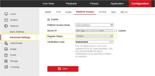
Figure 4-2 The Platform Access Page
The system will set LTS Connect as the platform access mode by default.
You can enable DHCP by following the steps below to allow allocating DNS address automatically.
Steps
DNS address will be allocated automatically.
When adding a device by scanning QR code or LTS Connect domain, if the result shows that the device has been added to another account, you should unbind it from the account before you can add it to your account.
Before You Start
Make sure the device and the phone running the Mobile Client are in the same local area network.
Steps
See Add Device(s) by Scanning Device QR Code or Add a Device by LTS Connect Domain for details.
Note
Unbinding the device via local GUI should be supported by the device.
You can share devices to other users. The recipient can access the devices according to the
permissions you grant them. You can also receive and use the devices shared by other users.
You can share a specific device to another LTS Connect user via the device’s QR code. You can also select the device permissions granted to the recipient to determine which operations the recipient can do on the device.
Steps
Option 1 Tap → Share Device → Share Device.
Option 2 On device list page, tap . You will enter the Recipient page.
page.
The recipient needs to send a device sharing application to you. After that, you’ll receive a notification about the application on your Mobile Client.
The device will be shared to the recipient. The recipient will be able to view the device on the device list.
You can share multiple devices to another LTS Connect user. You can also set the device permissions granted to the recipient to determine which operations the recipient can do on the device.
Steps
Option 1 Tap → Share Device → Share Device.
Option 2 1. Enter the Live View page.
Note
For details about how to enter the Live View page, see Start and Stop Live View.
Option 3 For security control panel, tap the device on device list page to enter the device details page and then tap .
The recipient’s account will be listed in the account list, and be automatically selected.
Note
The recipient can go to More → Account Management → My QR Code on his/her Mobile Client to get the QR code of his/her account.
Note
For devices linked with multiple cameras, you can select camera(s) for sharing.
.
Example
For example, if you select Live View and Remote Playback, the recipient will have the permissions to view live video and play back the video footage of the device.
A notification about the sharing will appear on the recipient’s Mobile Client. The recipient can tap the message, and then accept or reject the shared device.
You can add the frequently-used camera(s) to the favorites so that you can access them conveniently.
On the device list page, you can add the frequently-used camera(s) to the favorites so that you can access them conveniently.
Steps
Note
The added Favorites will be displayed on the device list page.
On the live view page, you can add frequently-used cameras to Favorites so that you can access them conveniently
Steps
Note
For details about how to enter the Live View page, see Start and Stop Live View
Note
The favorites name should be no more than 32 characters.
You can delete cameras in the favorites.
Steps
On the Settings page of a device, you can view and edit the device’s basic information, delete the device, upgrade device firmware, and configure other functions such as video and image encryption and changing device verification code.
Note
The available functions on the Settings page vary with different device types and device models.
The device verification code is used for verifying user identity, as well as encrypting a device’s videos (including live videos and recorded video files) and captured pictures. You can change the device verification code for the network camera and Mini Trooper (a kind of camera powered by battery).
Steps
Note
For details about how to encrypt a device’s videos and captured pictures, see Set Video and Image Encryption.
Note
If you have enabled the Video and Image Encryption function, new pictures and videos will be encrypted by the new verification code. However, the earlier encrypted pictures and videos still use the old verification code.
For security reasons, you can set the video and image encryption function to encrypt the videos or the pictures.
Steps
Note
Note
The default device verification code is usually on the device label. If no verification code found, enter the device verification code you created when enabling PT Cloud service. For details about enabling PT Cloud service, see Enable PT Cloud service for Device.
For a device added via LTS Connect Domain or Scaning QR code, if DDNS is enabled, the device’s streams will be accessed via IP address in priority. In this case, you can remotely configure device and the speed of streaming will be faster than that of streaming via PT Cloud service.
Steps
Device Domain Name
The default device domain name is the serial number of the device. If you want to edit it, the edited domain name should contain 1 to 64 characters, including numbers, lowercase letters, and dashes. And it should start with a lowercase letter and cannot end with a dash.
Port Mapping Mode
For details about setting port mapping, tap How to Set Port Mapping.
Note
The entered port number should be from 1 to 65535.
User Name
Enter the device user name.
Password
Enter the device password.
You can upgrade the firmware of a device to its latest version. If the latest version is detected, a red dot will appear on the Device Version field of the Settings page of the device.
Steps
The Mobile Client will download the upgrade file first and then start upgrading the device.
Note
You can also enable the Mobile Client to automatically download the upgrade file in Wi-Fi networks once a new device version is detected.
You can select a recorded audio file and set it as the custom audio prompt for the alarms sent
from the channels linked to specific models of DVR.
Steps
Note
The device should support this function.
For a device added via IP/Domain, you can use the Mobile Client as the device’s remote controller.
Steps
Note
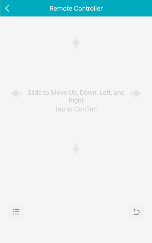
Figure 4-3 Remote Controller Page
After adding a device, you can set the parameters of the device, including basic information, time settings, recording schedule, etc.
View and Edit Basic Information
You can view and edit the basic information of a device.
Steps
Note
For details about adding device via IP/Domain, see Add a Device by IP/Domain.
Note
You should have configured DDNS for the device first. See Set DDNS.
Set Recording Schedule
You can set a recording schedule for a channel of a specific device.
Steps
.
Note
For details about how to enter the Live View page, see Start and Stop Live View.
Note
For details about adding device via IP/Domain, see Add a Device by IP/Domain.
Note
You should have configured DDNS for the device first. See Set DDNS.
Continuous
The video will be recorded automatically according to the time of the schedule.
Motion Detection
The video will be recorded when the motion is detected.
Alarm
The video will be recorded when the alarm is triggered via the external alarm input channels.
Motion Detection or Alarm
The video will be recorded when the external alarm is triggered or the motion is detected.
Motion Detection and Alarm
The video will be recorded when the motion and alarm are triggered at the same time.
Event
The video will be recorded when any event is detected.
Note
You can also set the recording type to detailed event type, which should be supported by the device. For details, refer to the user manual of the device.
Note
Up to 8 time periods can be configured for each day. And the time periods cannot be overlapped with each other.
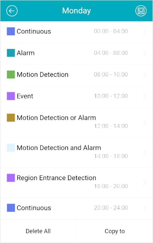
Figure 4-4 Setting Multiple Time Periods in a Day
Copy to Other Days Tap Copy to to copy all the time periods settings to the other days in the week.
Delete All Tap Delete All to clear all the configured time periods.
Configure Time Settings
You can select the time zone and set the time synchronization mode to Manual or NTP mode for the added device.
Steps
.
Note
For details about how to enter the Live View page, see Start and Stop Live View.
Note
For details about adding devices via IP/Domain, see Add a Device by IP/Domain.
Note
You should have configured DDNS for the device first. See Set DDNS.
NTP Synchronization
Synchronize time at a specific interval with the NTP server.
Note
For details about setting the NTP server details, refer to the user manual of the device.
Change Device Password
You can change the password of a device via the Mobile Client.
Steps
.
Note
For details about how to enter the Live View page, see Start and Stop Live View.
Note
For details about adding device via IP/Domain, see Add a Device by IP/Domain.
Note
You should have configured DDNS for the device first. See Set DDNS.
Caution
The password strength of the device can be automatically checked. We highly recommend you change the password of your own choosing (using a minimum of 8 characters, including at least three kinds of following categories: upper case letters, lower case letters, numbers, and special characters) in order to increase the security of your product. And we recommend you change your password regularly, especially in the high security system, changing the password monthly or weekly can better protect your product.
Proper configuration of all passwords and other security settings is the responsibility of the installer and/or end-user.
Configure Normal Event
You can enable a device’s normal event such as motion detection, video tampering alarm, video loss alarm, for the channels of the device.
Steps
Note
For details about adding device via IP/Domain, see Add a Device by IP/Domain
Note
You should have configured DDNS for the device first. See Set DDNS.
Configure Smart Event
You can enable the smart event for the channels of a device, including audio exception detection,
face detection, and intrusion detection, etc.
Steps
Note
The supported event types of smart event vary according to different devices.
Note
For details about adding device via IP/Domain, see Add a Device by IP/Domain.
Note
You should have configured DDNS for the device first. See Set DDNS for details.
Enable Temperature Measurement
You can enable the temperature measurement function for the thermal camera on the Mobile Client.
Steps
Note
This function is only available to the thermal camera.
Note
For details about adding device via IP/Domain, see Add a Device by IP/Domain.
Note
You should have configured DDNS for the device first. See Set DDNS.
Chapter 5 Video & Cloud Storage
With the Mobile Client, you can remotely view live videos of the added encoding devices (e.g., cameras, NVRs, and DVRs) and play back their video footage. If cloud storage is activated on the video devices, you can browse, search, play back, and download the video footage on cloud.
You can view live video of the devices’ connected cameras. And some basic operations are supported during live view, including picture capturing, manual recording, PTZ control, etc.
Live view shows you the live video getting from cameras. Perform the following task to start and stop live view.
Steps
Note
View Full Screen Live Video
Rotate the phone to view live video in full screen mode.
Switch Camera Swipe the live view page to the left or right to switch camera and view its live video.
Reselect Device for Live View
Note
You can select up to 256 cameras.
Switch to Playback Tap → Playback to switch to playback.
Note
For details about playback, see Playback.
You can adjust window division in different scenarios.
Tap ,
,
,
or
to set the window division mode to 1-window, 4-window, 9- window, 12-window, or 16-window respectively.
If the added camera number is more than the window division number, you can swipe left or right to see the rest.
Digital zoom adopts encoding technology to enlarge the image which will result in image quality damage. You can zoom in or zoom out the live video image as desired.
Tap to zoom in or zoom out the image.
Or spread two fingers apart to zoom in, and pinch them together to zoom out.
PTZ is an abbreviation for “Pan, Tilt, and Zoom”. With the PTZ Control functionality provided by the Mobile Client, you can make the cameras pan and tilt to the required positions, and zoom in or out the live video images. For some network cameras, you can also enable auto-tracking to make the camera pan, tilt, and zoom to track the detected moving objects.
Note
PTZ control should be supported by the camera.
Pan and Tilt a Camera
The Mobile Client allows you to pan and tilt a camera’s view.
Steps
Note
For details about how to start live view, see Start and Stop Live View.
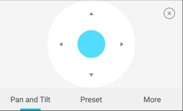
Figure 5-1 PTZ Conrol Panel
Set a Preset
A preset is a predefined image position which contains configuration parameters for pan, tilt, zoom, focus and other parameters. You can also set a virtual preset after enabling digital zoom. After you set a preset, you can call the preset and then the camera will move to the programmed position.
Steps
Note
See Pan and Tilt a Camera for details.
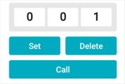
Figure 5-2 Set a Preset
Note
The preset No. should be between 1 and 256.
Adjust PTZ Speed
You can adjust the PTZ speed.
Steps
Other Functions
The PTZ Control panels provide other functions such as PTZ speed adjustment, auto-scan, focus control, iris control, and auto-tracking.
Tap More on the PTZ Control panel to view the functions.
Table 5-1 Other Functions
|
Icon |
Description |
|
|
Start/stop the auto-scan, which means to make the speed dome pan, tilt, and (or) zoom by a predefined route.
Note ●You can define the route on the device. For details, see the user manual of the device.
●The function should be supported by the
device. |
|
Icon |
Description |
|
|
|
|
|
Zoom control: |
|
|
Focus control: |
|
|
Iris control: |
|
|
Adjust PTZ speed. |
|
|
Enable/Disable auto-tracking. After enabled, when the camera detects a moving object, the camera will pan, tilt, and zoom to track the object until the object moves out of the field of view of the camera.
Note The function should be supported by the device. |
Two-way audio function enables the voice talk between the Mobile Client and devices. You can get and play not only the live video but also the real-time audio from the devices, and the devices can also get and play the real-time audio from the Mobile Client.
Steps
Note
Note
See Start and Stop Live View for details.
Note
If not, skip this step.
During live view, you can capture pictures of the live video and record video footage.
Steps
Note
See Start and Stop Live View for details.
Capture Picture Tap to capture a picture.
Record Video Footage
Tap to start recording video footage, tap again to stop.
The captured pictures and recorded videos will be saved in More → Pictures and Videos.
For devices added via IP/Domain, you can set its image quality to Fluent or Clear. You can also customize image quality for the devices.
Steps
Note
Note
See Start and Stop Live View for details.
Note
The icon vary with the actual video quality.
Confirm to confirm the custom settings.
Figure 5-3 Custom Settings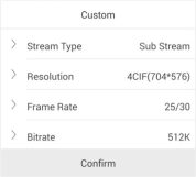
Note
Table 5-2 Recommended Configuration
|
Resolution |
1-ch |
2-ch |
4-ch |
Recommended Configuration |
|
H.264 (Software Decoding) |
||||
|
1080P |
√ |
√ |
|
Frame rate: 25fps; Bit rate: 4Mbps |
|
720P |
√ |
√ |
√ |
Frame rate: 25fps; Bit rate: 2Mbps |
|
4CIF |
√ |
√ |
√ |
Frame rate: 25fps; Bit rate: |
|
Resolution |
1-ch |
2-ch |
4-ch |
Recommended Configuration |
|
|
|
|
|
512Kbps |
|
H.264 (Hardware Decoding) |
||||
|
1080P |
√ |
√ |
√ |
Frame rate: 25fps; Bit rate: 4Mbps |
|
720P |
√ |
√ |
√ |
Frame rate: 25fps; Bit rate: 2Mbps |
|
4CIF |
√ |
√ |
√ |
Frame rate: 25fps; Bit rate: 512Kbps |
|
H.264+ (Software Decoding) |
||||
|
1080P |
√ |
√ |
|
Frame rate: 25fps; Bit rate: 4Mbps |
|
720P |
√ |
√ |
√ |
Frame rate: 25fps; Bit rate: 2Mbps |
|
H.264+ (Hardware Decoding) |
||||
|
1080P |
√ |
√ |
√ |
Frame rate: 25fps; Bit rate: 4Mbps |
|
720P |
√ |
√ |
√ |
Frame rate: 25fps; Bit rate: 4Mbps |
|
H.265 (Software Decoding. Hardware decoding is not supported.) |
||||
|
1080P |
√ |
√ |
|
Frame rate: 25fps; Bit rate: 2Mbps |
|
720P |
√ |
√ |
√ |
Frame rate: 25fps; Bit rate: 4Mbps |
|
4CIF |
√ |
√ |
√ |
Frame rate: 25fps; Bit rate: 256Mbps |
Usually three pre-defined image qualities are provided in the Mobile Client for LTS Connect device: Basic, Standard, and High Definition.
Steps
Note
The provided image quality types may vary with different devices.
Note
See Start and Stop Live View for details.
Note
The icon may vary with the actual image quality.
Basic
Basic image quality.
Note
Basic is the default image quality.
Standard
Standard image quality (the image quality is higher than that of Basic and lower than that of HD).
HD
High definition image quality (the image quality is the highest of the three).
In the fisheye view mode, the whole wide-angle view of the fisheye camera is displayed. Fisheye expansion can expand images in five modes: 180° panorama, 360° panorama, 4-PTZ, semisphere, and cylindrical-surface.
Steps
Note
The function is only supported by fisheye camera.
Note
See Start and Stop Live View for details.
Table 5-3 Mounting Type
|
Icon |
Description |
|
|
Wall Mounting |
|
Icon |
Description |
|
|
Ceiling Mounting |
Table 5-4 Fisheye Expansion Mode
|
Icon |
Description |
|
|
Fisheye view for ceiling mounting and wall mounting. In the Fisheye view mode, the whole wide-angle view of the camera is displayed. The mode is the vision of a fish’s convex eye. The lens produces curvilinear images of a large area, while distorting the perspective and angles of objects in the image. In this mode, you can pinch the fingers together to zoom out the image, and spread them apart to zoom in. |
|
|
Dual-180° panorama view for ceiling mounting. The distorted fisheye image is transformed to normal perspective image. In this mode, you can swipe to the left or to the right to adjust the field of view. |
|
|
360° panorama view for ceiling mounting and wall mounting. The distorted fisheye image is transformed to normal perspective image. In this mode, you can swipe to the left or to the right to adjust the field of view. |
|
|
4 PTZ Views for ceiling mounting and wall mounting. The PTZ view is the close-up view of some defined area in the Fisheye view or Panorama view. In this mode, you can pinch the fingers together to zoom out the image, and spread them apart to zoom in. You can also swipe the screen to perform pan and tilt movement. |
|
|
Semisphere-shaped view for wall mounting. In this mode, the whole wide-angle view of the camera is displayed. The lens produces curvilinear images of a large area, while distorting the perspective and angles of objects in the image. In this mode, you can drag the image to adjust the view angle, and pinch the fingers together to zoom out the image, and spread them apart to zoom in. |
|
|
Cylindrical-surface-shaped view for wall mounting. In this mode, the whole wide-angle view of the camera is displayed. The lens produces curvilinear images of a large area, while distorting the perspective |
|
Icon |
Description |
|
|
and angles of objects in the image. In this mode, you can drag the image to adjust the view angle, swipe to the left or to the right to adjust the field of view, as well as pinch the fingers together to zoom out the image and spread them apart to zoom in. |
You can open or close the door when viewing the live video of a video intercom device, a face recognition terminal, or a related camera of an access control device. This function allows you to check the visitor or the situation nearby the door before you open it.
Note
For the access control device’s related cameras, select a live view window and tap , and then enter the device verification code to open the door.
For the video intercom device, select a live view window and tap , and then enter the device verification code to open the door.
Note
The default device verification code is usually on the device label. If no verification code found, enter the device verification code you created when enabling PT Cloud service.
You can search the recorded video files stored in the added device for remote playback.
Normal playback refers to the playback based on timeline. You can search the camera’s recorded video files in a selected time period and then start playback.
Steps
Playback Date
Select a date.
Note
The date during which video files were recorded is marked with a yellow dot.
Playback Time
Set the start time point for the playback in the selected date.
Note
You can select up to 4 cameras.
Adjust Playback Time Slide the timeline to adjust the playback time.
Note
represents continuous recording and represents
event-triggered recording. You can determine the recording type (continuous or event-triggered) when setting recording schedule. For details, see Set Recording Schedule.
Scale up and down Timeline
Spread two fingers apart to scale up the timeline or pinch them together to scale down.

Figure 5-4 Timeline
Event playback refers to the playback based on the detected events, such as motion detection. You can select an event and then play back the event-related video footage. Duration playback, you can also save the event-related picture if it has been captured by the camera.
Before You Start
Make sure you have configured events for the selected camera.
Steps
Note
For details, see Normal Playback.
The event-related video footage within the latest 7 days will be displayed.
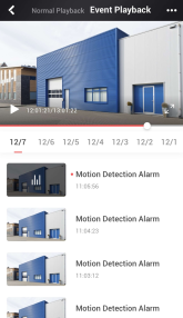
Figure 5-5 Event Playback Page
Note
Make sure you have configured the required event linkage action (capturing event-related picture) for the device. For details, see the user manual of the device.
During playback, you can capture pictures and record video footage.
Steps
Note
See Normal Playback for details.
Capture a Picture Tap to capture a picture.
Reccord Video Footage
Tap to start recording video footage, tap again to stop.
The captured pictures and recorded videos will be saved in More → Pictures and Videos.
For devices added by IP/Domain, you can set the image quality of playback for them.
Steps
Note
For details about adding device by IP/Domain, see Add a Device by IP/Domain.
Note
For details about starting playback, see Normal Playback.
Note
The icon may vary with the actual video quality.
Note
Table 5-5 Recommended Configuration
|
Resolution |
1-ch |
2-ch |
4-ch |
Recommended Configuration |
|
H.264 (Software Decoding) |
||||
|
1080P |
√ |
√ |
|
Frame rate: 25fps; Bit rate: 4Mbps |
|
720P |
√ |
√ |
√ |
Frame rate: 25fps; Bit rate: 2Mbps |
|
4CIF |
√ |
√ |
√ |
Frame rate: 25fps; Bit rate: 512Kbps |
|
H.264 (Hardware Decoding) |
||||
|
1080P |
√ |
√ |
√ |
Frame rate: 25fps; Bit rate: 4Mbps |
|
720P |
√ |
√ |
√ |
Frame rate: 25fps; Bit rate: 2Mbps |
|
4CIF |
√ |
√ |
√ |
Frame rate: 25fps; Bit rate: 512Kbps |
|
H.264+ (Software Decoding) |
||||
|
1080P |
√ |
√ |
|
Frame rate: 25fps; Bit rate: 4Mbps |
|
720P |
√ |
√ |
√ |
Frame rate: 25fps; Bit rate: 2Mbps |
|
H.264+ (Hardware Decoding) |
||||
|
1080P |
√ |
√ |
√ |
Frame rate: 25fps; Bit rate: 4Mbps |
|
720P |
√ |
√ |
√ |
Frame rate: 25fps; Bit rate: 4Mbps |
|
H.265 (Software Decoding. Hardware decoding is not supported.) |
||||
|
1080P |
√ |
√ |
|
Frame rate: 25fps; Bit rate: 2Mbps |
|
720P |
√ |
√ |
√ |
Frame rate: 25fps; Bit rate: 4Mbps |
|
4CIF |
√ |
√ |
√ |
Frame rate: 25fps; Bit rate: 256Mbps |
For the cameras linked to a DVR or NVR, you can adjust the playback speed for them as required.
Note
The function should be supported by the device.
During playaback, you can swipe the toolbar at the bottom to view the hidden icons, and then tap
to set the playback speed to 1/8X, 1/4 X, 1/2 X, 1X, 2X, 4X, and 8X. X here refers to the original playback speed.
During playback of the cameras linked to a DVR or NVR, you can download a specific video segment as evidence if it contains important information about incidents such as violent crimes in case of the need for settling disputes or legal cases.
Steps
Note
The function should be supported by the device.
By default, the video segment which lasts 130 seconds (from 10 seconds before the tapping, to 120 seconds after that) will be automatically selected for download. For example, if you tap when the video footage is played to 00:00:30, the segment from 00:00:20 to 00:02:30 will be selected.
Note
In special occasions when 130-seconds duration is not available to be selected following the above-mentioned rule, the segment will extend afterwords or backwards until the segment duration reaches 130 seconds. For example, if you start downloading from the very beginning of the video footage, the selected segment will be from 00:00:00 to 00:02:10.
Note
The duration should not be shorter than 10 seconds.
Note
If the segment is encrypted, you should enter the device verification code before you can preview it. For details about video encryption, see Set Video and Image Encryption.
Note
Downloading at the background is supported. Download task(s) continues if you exit the Download page or the Mobile Client.
With cloud storage, your cameras, DVRs, and NVRs can upload recorded video clips to the cloud automatically. You can easily access, play, and download the video footage of your video devices on cloud.
Note
Cloud storage service is not available in all countries or regions.
You can enable/disable cloud storage service for a specific channel of a device supporting storing video footage on cloud. You can also view details of the cloud storage service package, including service package type, effective period, and status (activated or expired).
Before You Start
Make sure your installer has activated the cloud storage service for your device. Otherwise, you cannot enable cloud storage.
Steps
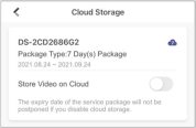
Figure 5-6 Cloud Storage
You can play back video footage stored on cloud.
Note
Make sure your installer has activate cloud storage service for your devices and you have enabled it.
See details in Enable/Disable Cloud Storage Service for a Channel.
To play back the video footage on cloud:
Note
See instructions in Normal Playback.
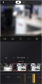
Figure 5-7 Playback – Cloud Storage
Note
See details in Download Video Footage from Cloud.
The Mobile Client allows you to browse through the video footage stored on cloud of each date to quickly locate the footage you need. And you can download the video footage to your phone.
Before You Start
Note
Make sure your installer has activate cloud storage service for your devices and you have enable it. See details in Enable/Disable Cloud Storage Service for a Channel.
Steps
Note
See details in Play Back Video Footage on Cloud.
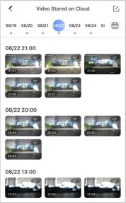
Figure 5-8 Video Stored on Cloud
Note
The date marked with a blue dot is the date during which video footage is recorded.
Chapter 6 Manage Access Control Devices
Access control is the selective restriction of access to a place or other resources. After adding access control devices to the Mobile Client, you can remotely control the doors, and configure duration in which the doors remain open. You can also filter and view access control device’s logs, which provide the information of access events and related alarms, such as access controller tampering alarms.
Besides the above-mentioned functionality, you can change the supper password of the access control device. And for face recognition terminals, you can enable fingerprint authentication or facial authentication to open doors.
1.
Note
On the device list page, tap on the right of the access control device to enter the door control page.
The door icon varies with different door status.
Remain Open
Keep the door open.
Open Door
Open the door for a configurable time period. When the time period expires, the door will close.
Note
On the device list page, tap → Door Open Duration to set door open duration.
Remain Closed
Keep the door closed. In this status, the door can only be opened by super card or super password.
Note
For details about super cards, see the user manual of the access control device.
Note
On the device list page, tap → Change Password to change the super password.
The Mobile Clientsupports controlling the status of the access control devices’ related doors by the super password of the device.
Steps
Note
You can change the super password. See Change Super Password for details.
Note
The door icon varies with different door status.
Remain Open
Keep the door open.
Open Door
Open the door for a configurable time period. When the time period expires, the door will close.
Note
For details about configuring the time period, see Set Door Open Duration.
Remain Closed
Keep the door closed. In this status, the door can only be opened by super card or super password.
Note
For details about super card, see the user manual of the access control device.
Note
The door status will change.
You can set the door open duration for the access control device. When the duration expires, the door will close automatically.
Steps
If you tap Open Door in the door control page, the door will open for the configured time duration.
Note
For details about controlling door status, see Control Door Status.
The Mobile Client allows you to change the super password of the access control device, which can be used to open all the access control points (e.g., doors), even when the access control point is in remaining closed status.
Steps
Note
For details about super password of the access control device, see the user manual of the device.
Note
If it is the first time to set the super password, skip this step.
Note
The password should contain 6 numbers.
You can view the access control device’s logs including the access control events and alarm information. You can also filter the logs.
Steps
![]()
Figure 6-1 The Icon Representing Door
The log list will be displayed on the Log section of the page.
Refresh Log List Swipe the log list downward to refresh it.
View All Logs Tap View All Logs to enter the Log page and view all access control device logs.
Filter Logs On the Log page, tap Filter and then set the filtering condition (time and event type) to filter.
After adding face recognition terminals to the Mobile Client, you can enable opening door via fingerprint authentication or face recognition.
Note
Your phone or tablet should support fingerprint authentication or face authentication.
After adding a face recognition terminal, when you open the device’s related door for the first time, a prompt will pop up asking you whether to enable opening door via fingerprint authentication or face recognition or not. You can follow the prompt to enable this function.
If you have ignored the above-mentioned prompt, you can tap to enter the Settings page, and then switch on the function.
Chapter 7 Facial Data Management
For the DeepinMind server on the same LAN with the Mobile Client, you manage the facial data stored in it via the Mobile Client. The facial data can be used for facial comparison in related applications.
Before You Start
Perform the following task to upload facial data to the DeepinMind server.
Steps
Note
For the first time usage, you should enter the user name and password of the device to verify you identity first. Once verified, the verification is not required afterwords.
The face picture will be uploaded to the server and the server will start recognizing the facial data. Once recognized, the face picture will be displayed in the face library.
Chapter 8 Video Intercom
The Mobile Client supports video intercom functions. Video intercom is an audiovisual communication and security technique used in a building or a small collection of buildings. With microphones and video cameras at both sides, it enables the intercommunication via video and audio signals.
If no one answers the call via the indoor station for a while, the call will be forwarded to the Mobile Client. You can answer the call, view the live video of the door station, as well as open the door.
Steps
Note
Up to 6 users can view the live video of the same door station at the same time. If there’s already been 6 users viewing the live video, you can only use the audio function of the video intercom device.
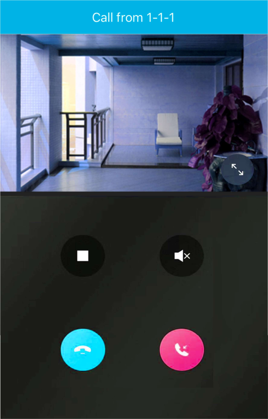
Figure 8-1 Call Page
Stop/Restart Live View
Tap to stop the live view. And tap
to restart it.
Mute Tap to mute the live video.
Open Door Tap to open the door.
Digital Zoom Pinch two fingers together to zoom in the live video image, and spread them apart to zoom out.
On the device details page of the video intercom devices, you can perform the operations including viewing the live videos streamed from the cameras linked to the door stations or doorbells, starting two-way audio, playing back video footage, viewing call logs and history events, controlling doors linked to door stations, and controlling relays connected to the indoor station.
Tap the video intercom device on the device list to enter the device page.
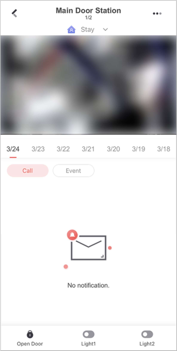
Switch Scene
Figure 8-2 Video Intercom Device Page
You can tap to set Stay, Away, Sleep, or Custom as the scene for arming the detectors linked to the door station.
Stay
When the people stays inside the detection area, turn on the Stay mode to turn on all the perimeter burglary detection (such as perimeter detector, magnetic contacts, curtain detector in the balcony). At the meantime, the detectors inside the detection area are bypassed (such as PIR detectors). People can move inside the area and alarm will not be triggered.
Away
When all the people in the detection area leave, turn on the Away mode to arm all zones in the area after the defined dwell time. For example, assume that you have set your apartment as a zone, you can set the zone status to Away when you go to work.
Sleep
The detectors in the bedroom is bypassed while the detectors in other rooms are armed. In this scene, all the perimeter burglary detection in other rooms are turned on, while no alarms will be triggered within the bedroom.
Live View
The live video will start playing when you enter the device details page. You switch live videos if multiple door stations are linked to the video intercom device.
During live view, you can tap the image to show the hidden icons, and then perform operations such as starting two-way audio, capturing picture, recording, full-screen live view, and setting image quality.
Note
For details about the above-mentioned operations during live view, see Start Two-Way Audio, Capturing and Recording, Set Image Quality for Device Added by IP/Domain, and Set Image Quality for LTS Connect Device.
Playback
Tap → Playback to start playing back video footage.
View Call Logs and Events
You can view the call logs and device-related events in the latest 7 days (the events or call logs of the current day will be displayed by default).
Control Door
You can tap to control the door linked to the video intercom device.
Control Relay
You can tap to control the connected relays of an indoor station remotely.
To set up relay name and open duration, go to the Settings page of the video intercom device. Open duration for a relay:
Motion detection is a way of detecting motion in a surveillance scene by analyzing image data and differences in a series of images. After setting motion detection area for Wi-Fi doorbell, the device will be able to detect the object in motion and at the same time the Mobile Client will receive an event notification about the motion detection alarm.
Steps
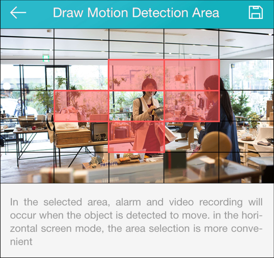
Figure 8-3 Draw Motion Detection Area
Low
Moving persons, large moving pets, and any other large moving objects in the motion detection area will trigger the alarm, while smaller objects will not.
Medium
Moving small pets and any other medium-sized moving objects in the motion detection area will trigger the alarm, while smaller objects will not.
High
Moving insects, moving leaves, and any other larger objects will trigger the alarm.
What to do next
Go back to the Notification page and make sure Notification is enabled.
Note
For details about how to enabling notification, see Enable Event Notification
You can set video intercom volume as required.
Steps
Note
Only video intercom devices support this function.
You can add a smart chime to the Mobile Client and link it with a doorbell so that the doorbell will standby for longer and be more responsive.
Add a Smart Chime
After adding a smart chime, you can tap the smart chime in the device list to mute all devices with
one tap and enable/disable Ring Alert for linked doorbells.
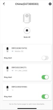
Figure 8-4 View Smart Chime
Link Smart Chime with Doorbell
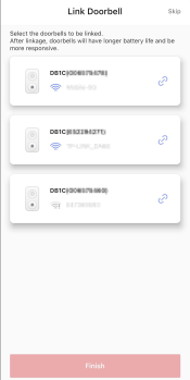
Figure 8-5 Link Doorbell
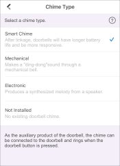
Figure 8-6 Link Smart Chime
Note
When you link a smart chime with a doorbell, make sure they are near to each other and they are both online.
Chapter 9 Notification
On the Notification tab, you can view the event notifications and call logs of the video intercom devices.
Note
In the mobile client, each device can only send one alarm per minute. It’s a mechanism to not overload the servers. So for example, a camera will send a notification about a line crossing but if someone crosses the same line 20 seconds later on the same camera, it won’t send another alert/notification. It can only send 1 alert per device, per minute.
You can allow the Mobile Client to receive and push notifications of the events detected by a device. If you want to block notifications during specific time, you can set a notification schedule to define the time period(s) during which the Mobile Client is allowed to receive event information and push them to you. You can also set notification mode to avoid the disturbance of push notifications (and the audio and strobe light alarm) while still being able to receive event information on the Notification page.
Before You Start
Make sure you have configured event settings on device (except for the video intercom device). See the user manual of the device for details.
Steps
Note
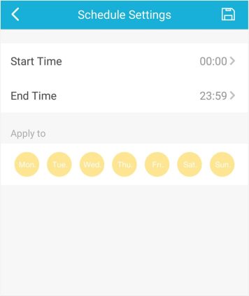
Figure 9-1 Schedule Settings Page
Note
The date(s) marked in blue is selected.
Note
The function should be supported by the device.
Intensive
Intense warning for the intrusion.
Soft
Soft warning for the intrusion.
Mute
No audible warning.
You can check event notifications on the Notification page when events are detected by the devices. The unread notifications are marked with a red dot.
Before You Start
Steps
View and Download Event-related Picture
If there are multiple event-related pictures, you can swipe left/right to switch pictures. You can also tap a picture and then tap to download the picture.
Zoom In/Out Event- related Picture
Tap the picture, and then spread two fingers apart to zoom in the picture and pinch them together to zoom out, or double-tap the picture to zoom in or zoom out.
Note
need to enter the device verification code before you can view the picture.
View Event-related Video Footage
Tap Playback to view the video footage.
Note
Make sure you have configured the event linkage action for recording video for the device. See the user manual of the device for details.
View Live Video Tap Live View to view the live video of the device.
Note
The device should support this function.
Mark All Events as Read
Tap , and then tap Mark as All Read to mark all event information as “already read”.
Clear All Events Tap , and then tap Clear All.
Delete a Specific Event
Tap and hold an event notification until a prompt pops up, and then tap Delete to the prompt to delete the notification.
You can check Pyronix notifications on the Notifications page when there are any Pyronix notifications. The unread notifications are marked with a red dot.
Steps
Mark All Events as Read
Tap → Mark as All Read, and then tap to mark all event information as “already read”.
Clear All Events Tap → Edit → Clear All to clear all event notifications.
Delete a Specific Event
Tap and hold an event notification until a prompt pops up, and then tap Delete to the prompt to delete the notification.
Or, swipe from the right end of the card that displays the event notification towards the left, and then delete this event notification.
You can check call notifications on the Notifications page when someone calls. The unread notifications are marked with a red dot.
Steps
Mark All Events as Read
Tap → Mark as All Read, and then tap to mark all event information as “already read”.
Clear All Events Tap → Edit → Clear All to clear all event notifications.
Delete a Specific Event
Tap and hold an event notification until a prompt pops up, and then tap Delete to the prompt to delete the notification.
Or, swipe from the right end of the card that displays the event notification towards the left, and then delete this event notification.
In Notifications → Service, you can view the notifications related to services offered by your Service Provider via the LTS Connect Pro platform, including applications for device handover, device authorization and permissions, and device password reset. You can also view notifications about cross-device linkages, device exceptions and corresponding handling results, and logs about Service Provider’s operations on your devices.
Note
LTS Connect Pro is a cloud service platform for the Service Providers (installation companies) that configure and maintain your devices and provide value-added services for you.
You can accept the invitation from the Service Provider to be the owner of a specific site. Go to Notifications → Service.
You can tap on an invitation to view the details such as the site and the devices authorized to the Service Provider, and then tap Agree to accept the invitation and therefore become the owner of the site.
If a Service Provider hands over devices to you or applies for device permissions on the LTS Connect Pro platform, you will receive an application notification. After you approve the application, the Service Provider will be able to provide device configuration and maintenance services based on the permissions you granted.
Steps
Note
After handover, your Service Provider does not have any permissions to operate or configure the devices. Service Provider usually applies for device permissions so as to configure and maintain the devices for you. If your Service Provider has applied for the permissions, you need to accept it in device authorization application.
Note
Note
including receiving events from devices, responding to events, and sending out emergency dispatches (if needed).
If a device that you rent from the Service Provider is blocked or unblocked by the Service Provider, you will receive a notification about that.
Note
If a rent device is blocked by the Service Provider, you are not allowed to operate the device via the Mobile Client. In this case, you can contact the Service Provider and ask her/him to unblock the device if required.
For such a notification, you can view the Service Provider who block/unblock the device and the site where the device is added.
You can receive and view the exception notifications of your devices that are managed by the Service Provider.
After your Service Provider handles an exception, you will also be notified of the handling result. You can see all exception notifications in Notifications → Exception.
Under system notifications, you can view linkage notifications. Linkage refers to the process in which an event detected by a resource triggers actions in other resources. The linkage can be used for notifying security personnel, upgrading security level, saving evidence, etc., when specific events happen. You can view notifications about linkages in Service Notifications.
Note
Go to Notifications → System to view linkage notifications. You can tap on each notification to view the detected event, event time, devices in the linkage, and triggered actions.
Chapter 10 System Settings
This section introduces system settings of the Mobile Client, including hardware decoding, floating live view, resuming latest live view, etc.
If push notification is enabled, the Mobile Client will push alarm notifications related to the added devices to you.
Note
For details about alarm notifications, see Notification for details.
Tap More → Settings to enter the Settings page, and then enable the push notification.
If the function is enabled, the Mobile Client will remember the device parameters you set. Take video and image encryption for an example, you only need to enter the device verification code for once to view the encrypted live view, playback, or picture.
Note
If you enable this function, the Mobile Client will run automatically and receive alarm event information when the phone or tablet is powered on.
Tap More → Settings to enter the Settings page and then enable the function.
Note
The power consumption of the phone or tablet may increase.
For devices added via IP/domain, the Mobile Client allows you to generate a QR code containing
the information of up to 32 devices. The QR code can be used to quickly add multiple devices. For example, if user A has generated a QR code containing the information of 10 devices, user B can scan the QR code to batch add the 10 devices to his or her account.
Steps
Note
Only devices added by IP/domain support this function.
The QR code picture will be generated.
Hardware decoding provides better decoding performance and lower CPU usage when you play high definition videos during live view or playback.
Tap More → Settings to enter the Settings page, and then enable the function.
Note
The Mobile Client automatically calculates the network traffic consumed during live view and playback. You can check the mobile network traffic and Wi-Fi network traffic separately.
Tap More → Settings to enter the Settings page, and then tap Traffic Statistics.
You can generate a QR code with Wi-Fi information, and then use a network camera or wireless
doorbell to scan the QR code to connect the device to the Wi-Fi network.
Steps
Note
Connecting device to a Wi-Fi network by scanning QR code should be supported by the device.
Wi-Fi Name
Enter the SSID of the Wi-Fi network.
Password
Enter the password of the Wi-Fi network.
Encryption
Select the encryption type as the one you set for the router.
Note
If you select NONE as the encryption type, the password of the Wi-Fi network is not required.
What to do next
Use a network camera or wireless doorbell to scan the QR code to connect the device to the Wi-Fi network.
If you enable this function, floating live view window(s) will be displayed on the device list page when you select one or more device(s). You can preview the live video(s) in the floating window(s).
Note
Tap More → Settings to enter the Settings page and then enable the function.
If you enable the function, the latest live view will be resumed each time you enter the Mobile Client. The window division mode, and the live view windows’ sequence (if in multiple-window
mode) will also be restored.
Tap More → Settings to enter the Settings page, and then enable the function.
If the Mobile Client is installed on an Android tablet, you can enable tablet mode so that the interfaces will be displayed in landscape mode by default.
Tap Me → Settings to enter the Settings page and then enable the function.
Note
After enabling tablet mode, you should restart the Mobile Client to make the settings effective.
Channel-zero, known as virtual channel, can show the videos from all channels of the device, reducing the bandwidth while simultaneously previewing from multi-channel. It can acquire image information and save bandwidth for transmission through encoding and configuring output images.
Tap More → Settings and then enable the Mobile Client to display channel-zero.
If you enable Auto-Donwload Upgrade File, the Mobile Client will automatically download the upgrade file in Wi-Fi networks, which helps speed up the device upgrade process.
Note
For details about upgrading device, see Upgrade Device Firmware.
Tap More → Settings to enter the Settings page and then enable the function.
You can record audio files for setting them as the custom audio prompts for the alarms sent from the channels linked to specific models of DVR.
Perform this task to record an audio file.
Steps
Note
By default, the file name is the time (accurate to second) when recording stops.
Rename Audio Long press and then tap Rename to rename the audio file.
Delete Audio Long press and then tap Delete to delete the audio file.
What to do next
Set custom audio prompt for the alarms sent from the channels linked to specific models of DVR. For details, see Set Custom Audio.
Chapter 11 Other Functions
The Mobile Client provides other functions, including fingerprint authentication and management of the recorded videos and captured pictures.
In Picture and Video Management module, you can view and mange the recorded (or clipped) video footage and the captured pictures.
Tap More → Pictures and Videos to enter the Pictures and Videos page and then you can perform the following operations.
You can rotate the phone to view the video in landscape mode.
You can show the QR Code for downloading the Mobile Client to others.
Tap More → Share LTS Connect to view the QR code. After that, you can let others scan the QR code to download the Mobile Client.
