Geovision GV-VMS Setup Guide, GV-VMS V18 is a full-featured, AI-powered software series. It includes not only all of capabilities of GV-VMS V17 series, but also incorporates events from face detection, face recognition and AI-powered IP cameras for an all-inclusive video management.
GV-VMS V18 is a comprehensive video management system that records video from GeoVision and third-party IP devices. The live view and playback layout can be easily adjusted with the intuitive drag-and-drop function. GV-VMS V18 comes with a variety of intelligent video analytics to offer precise monitoring and to reduce the need for manual supervision. The built-in WebCam Server allows users to remotely access live view and recordings from anywhere using Web browsers, mobile app and GV-Remote ViewLog program. Compatibility with GeoVision central monitoring systems and support for a wide selection of third-party ONVIF cameras make GV-VMS a versatile and effective surveillance solution.
GV-VMS V18 is a paid software that can connect up to 32 channels of GV-IP devices with the initial license, and up to 64 channels with an added GV-VMS Pro license. Additional licenses are required if you need to connect with third-party IP devices.
GV-VMS is a comprehensive video management system, and requires a purchased license starting from V18.1, that records up to 64 channels of GeoVision and/or third-party IP devices. Make sure your purchased GV-Dongle or software license has been inserted into or activated on the PC prior to running GV-VMS.
IMPORTANT:
s
![]()
Û
![]()
GV-VMS
D
1
Introduction
Welcome to the GV-VMS Quick Start Guide. Through this guide, you will learn the basic settings of GV-VMS. For the complete instructions, refer to GV-VMS User’s Manual.
• GV-VMS V17 (Free 32 GV Channels)
GV-VMS V17 series supports connection of up to 64 IP channels, and up to 32 channels of GeoVision IP devices are for free. If you need to connect more than 32 channels of GeoVision IP devices or connect with third-party IP devices, additional licenses are required.
|
Supported Devices |
Channels |
License |
|
GV-IP Devices Only |
32 ch |
No license required |
|
64 ch |
GV-VMS Pro license required, 32 ch per license |
|
|
|
16 ch |
Trial Version: 16 channels of 3rd-Party IP devices |
|
GV + 3rd-Party IP |
32 ch |
3rd-Party or HD DVR license required, in increments of 1 ch |
|
Devices |
64 ch |
2 licenses required: •GV-VMS Pro license, 32 ch per license.
•3rd-Party or HD DVR license, in increments of 1 ch.
|
|
Note: |
||
1
![]()
• GV-VMS V18 (for AI Integration)
GV-VMS V18.1 or later is a paid software for AI integration that supports connection of up to 64 IP channels, and can connect up to 32 channels of GeoVision IP devices upon initial purchase. If you need to connect more than 32 channels of GeoVision IP devices or connect with third-party IP devices, additional licenses are required.
|
Supported Devices |
Channels |
License |
|
|
32 ch |
Initial license required |
|
GV-IP Devices Only |
64 ch |
2 licenses required: •GV-VMS V18.1 or later initial license
•GV-VMS Pro license, 32 ch per license
|
|
|
4 ch |
Trial Version: 4 channels of 3rd party IP devices (30 days, a license key required) |
|
GV + 3rd-Party IP Devices |
32 ch |
2 licenses required: •GV-VMS V18.1 or later initial license
•3rd-Party or HD DVR license, in increments of 1 ch
|
|
64 ch |
3 licenses required: •GV-VMS V18.1 or later initial license
•GV-VMS Pro license, 32 ch per license
•3rd-Party or HD DVR license, in increments of 1 ch
|
|
|
Note: |
||
Note for GV-VMS V18.3.1 or later:
2
1
Introduction
Below are the minimum PC requirements for connecting GV-VMS with 32 and 64 channels of GeoVision and 3rd party IP cameras (dual streams).
• GV-VMS V17
|
CPU |
GV-VMS (Up to 32 Channels) |
GV-VMS Pro (Up to 64 Channels) |
|
OS |
64-bit Windows 8 / 8.1 / 10 / 11 / Server 2012 R2 / Server 2016 / Server 2019 |
|
|
CPU |
4th Generation i5-4670, 3.4 GHz |
4th Generation i7-4770, 3.4 GHz |
|
Memory |
8 GB RAM |
16 GB RAM |
|
Processor Graphics |
To obtain the maximum frame rate possible, see GPU Decoding specifications here. |
|
Note:
• GV-VMS V18
|
CPU |
GV-VMS (Up to 32 Channels) |
GV-VMS Pro (Up to 64 Channels) |
|
OS |
64-bit Windows 10 / 11 / Server 2016 / Server 2019 / Server 2022 |
|
|
CPU |
4th Generation i5-4670, 3.4 GHz |
4th Generation i7-4770, 3.4 GHz |
|
Memory |
8 GB RAM |
16 GB RAM |
|
Processor Graphics |
To obtain the maximum frame rate possible, see GPU Decoding specifications here. |
|
Note:
3
The data transmitting capacity of GV-VMS depends on the number of Gigabit connections available. The numbers of Gigabit network cards required to connect 64 channels are listed below according to the resolution and codec of the source video.
|
Codec |
Resolution |
Bitrate Used (Mbps) |
Total FPS for 64 ch |
Gigabit Network Cards Required |
Max. Channels Supported per Network Card |
|
H.264 |
1.3 MP |
5.05 |
1920 |
1 |
Max. 64 ch / card |
|
2 MP |
7.01 |
1920 |
1 |
Max. 64 ch / card |
|
|
3 MP |
10.48 |
1280 |
1 |
Max. 64 ch / card |
|
|
4 MP |
11.65 |
960 |
2 |
Max. 50 ch / card |
|
|
5 MP |
16.48 |
640 |
2 |
Max. 38 ch / card |
|
|
8 MP |
17.14 |
1600 |
2 |
Max. 38 ch / card. |
|
|
12 MP |
16.67 |
960 |
2 |
Max. 38 ch / card |
|
|
H.265 |
2 MP |
5.90 |
1920 |
1 |
Max. 64 ch / card |
|
3 MP |
7.06 |
1920 |
1 |
Max. 64 ch / card |
|
|
4 MP |
9.44 |
1600 |
1 |
Max. 64 ch / card |
|
|
5 MP |
7.52 |
1920 |
1 |
Max. 64 ch / card |
|
|
8 MP |
9.83 |
1280 |
1 |
Max. 64 ch / card |
|
|
12 MP |
9.85 |
1280 |
1 |
Max. 64 ch / card |
|
|
MJPEG |
1.3 MP |
32.36 |
1920 |
3 |
Max. 22 ch / card |
|
2 MP |
44.96 |
1920 |
4 |
Max. 16 ch / card |
|
|
3 MP |
38.73 |
1280 |
4 |
Max. 18 ch / card |
|
|
4 MP |
40.35 |
960 |
4 |
Max. 17 ch / card |
|
|
5 MP |
30.48 |
640 |
3 |
Max. 22 ch / card |
|
|
8 MP |
58.52 |
1600 |
6 |
Max. 12 ch / card |
|
|
12 MP |
65.98 |
960 |
6 |
Max. 11 ch / card |
Note: The network requirements may vary depending on the bitrate of the streams.
4
1
Introduction
Before You Start
For optimal performance of your system, it is important to follow these recommendations before installing the GV-VMS:
Frame rate limit in a single hard disk
|
Video Resolution |
H.264 |
H.265 |
||
|
Frame Rate (fps) |
Bitrate (Mbps) |
Frame Rate (fps) |
Bitrate (Mbps) |
|
|
1.3 MP (1280 x 1024) |
660 |
5.05 |
N/A |
N/A |
|
2 MP (1920 x 1080) |
660 |
7.01 |
660 |
5.90 |
|
3 MP (2048 x 1536) |
440 |
10.48 |
660 |
5.35 |
|
4 MP (2048 x 1944) |
330 |
11.65 |
550 |
7.74 |
|
5 MP (2560 x 1920) |
220 |
16.48 |
660 |
6.73 |
|
8 MP (3840 x 2120) |
550 |
14.13 |
440 |
9.83 |
|
12 MP (4000 x 3000) |
330 |
14.47 |
440 |
9.85 |
Note: The data above was determined using the bitrate listed above, hard disks with average R/W speed above 110 MB/s.
The frame rate limit is based on the resolution of video sources. The higher the resolutions, the lower frame rates you can assign to a single hard disk. In other words, the higher the frame rates you wish to record, the more hard disks you’ll need to. For detailed information of recording frame rates, refer to the user’s manual of the IP camera that you wish to connect to.
5
Installing GV-VMS
D
d. Audio inputs and outputs
:■ c omputer
u Disk drives
*1, Display adapters
j V DVR-Devices
C GV-Series USB Protector
Human Interface Devices
> urf IDEATA/ATAPI controllers
6
1
Introduction
In the main screen of GV-VMS, the main setting buttons are located in the top-right corner.
![]()
Login ID Home Toolbar
Version Information
Storage Space … … .
a I r Audio ViewLog Exit

Name Description
Login ID Click to manage accounts and passwords for accessing GV-VMS.
Audio Click to control the volume of your PC.
Home Shows the live view of connected cameras.
ViewLog Shows a timeline of recorded events for playback.
Brings up these options when Home is selected:
Toolbar • Content List: Configure live view layout, of cameras, I/O devices and E-Maps.
Brings up these options when ViewLog is selected:
Exit Click to Minimize or Exit GV-VMS.
Geovision GV-VMS Setup Guide
Read More : CCTV Super Password
7
When logging in for the first time after installing GV-VMS, the Automatic Setup dialog box appears. Follow the steps below to add IP cameras.
desired cameras and click Apply.
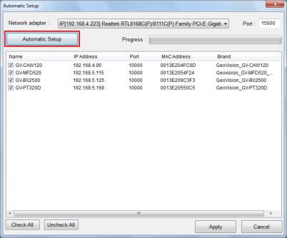
modify the login info of cameras if needed.
3. Cameras added are now listed in the IP Device List.

Status icons illustrated:
|
* Connected |
The camera is connected. |
|
* Connecting |
GV-VMS is trying to connect to the camera. |
8
2
Getting Started
& Connection Failed
O Inactive Camera
v Started Monitoring
v Pre-Rec Enabled
Unable to connect to the camera. Move the cursor onto the red
icon to see the error message.
The camera is inactive. Click the checkbox to connect.
The camera is under monitoring.
Pre-recording is enabled.
> Configure O > Camera Install.
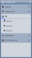
After adding cameras, you can access camera live view by dragging the camera in the Content List to the live view grid.
Click Home > Toolbar > Content List ■ ■. Then click Camera to see the list of
cameras added, and drag the desired cameras to the live view grid.
![]()
For details, see Chapter 4 Live View in this Quick Start Guide.
9
After setting up cameras and the live view, be sure to start monitoring the cameras to activate the following functions.
Recording (See Section 3.1)
Video Analysis (See Chapter 5)
I/O Applications (See Section 7.1)
To start monitoring of connected cameras, click Toolbar EkE > Monitor > Start All
Monitoring or select individual cameras.
To see how to access recorded videos, refer to Chapter 6 Video Playback and Backup.
Note: If you have set a schedule, you can select Start Schedule Monitoring. The schedule takes precedence and the functions listed above will enable and disable accordingly. See 7.2 Setting up Schedules.
10
3
Camera Setup
To configure the recording settings of connected cameras
Configure & > System Configure > Record Setting.
click Home > Toolbar >
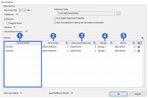
The frame rate for General Event and Urgent Event can be defined in the camera’s General Setting page. See General Setting in 3.2 Configuring Camera Settings. Normally, you would set a higher frame rate for Urgent Events (e.g. full frame) and a lower frame rate for General Events (e.g. key frame only).
Note: By default, the recording mode is set to Motion Detection and the Recycle function is enabled with the Recycle Threshold set to 32 GB.
11
For details on Motion Detection settings, see Setting up Motion Detection, Chapter 1, GV- VMS User’s Manual.
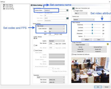
To configure camera settings, click the Setup button E3 of an active camera in the IP Device List. The settings available vary depending on the camera’s firmware and whether the camera is connected or not.
There are three setup dialog boxes in the left menu of the camera’s setting dialog box: Video Setting, Audio Setting, and General Setting. Clicking the Finger button E3 to apply the same settings to all connected cameras.
[Video Setting]
In Video Setting, you can configure the camera name, codec, frame rate, GOP, bitrate, resolution, trigger output, lens, video attributes and image orientation of the camera. Note that changes made to the Video Setting dialog box will change the settings on the IP camera.
12
3
Camera Setup
[Audio Setting]
In Audio Setting, you can configure audio functions for live view and recording, which are disabled by default.
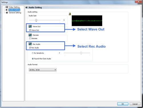
Note: After Wave Out is enabled here, you can enable audio on the live view of the camera by clicking the Tools icon “?’■ and select Set to Wave Out.
13
[General Setting]
In General Setting, you can configure network timeout, on-demand display, live view frame rate, and recording frame rate settings.
Set live view frame rate
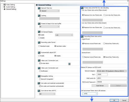
Set recording frame rate
Note:
14
3
Camera Setup
and General event. Refer to the step above for details. Make sure the related settings are configured accordingly in the Recording Settings dialog box as described in step 3 of 3.1 Configuring Recording Settings.
For details on Video Setting, Audio Setting, and General Setting, see Configuring Individual IP Cameras, Chapter 2, GV-VMS User’s Manual.
15
![]()
A message appears. Click Yes if you want to automatically assign the cameras to the new layout.
16
_4_ Live View
Place the mouse cursor on the camera live view to see the icons below.

|
Icons |
Functions |
|
Instant Play H |
Plays back the video recorded. |
|
Snapshot® |
Captures a snapshot of the current live view. |
|
Talk Back Toggle |
Talk to the surveillance site. For details, refer to [The behavior of the talk |
|
/ Push-to-Talk ‘®’ |
back button] in 1.6.1 Configuring General Setting, GV-VMS User’s Manual. |
|
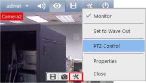
Tools |
Includes the following options: •Monitor: Starts monitoring of the camera.
•Measure temperature: For GV-VMS V18.3.2 or later and GV- TMEB5800 only. After the thermography rules are set up on the camera Web interface, select this option to trigger the alarms when the detected temperature exceeds the pre-defined threshold.
•Properties:
–Show Caption: Shows camera name on live view using the specified font size.
–Keep Image Ratio: Locks aspect ratio of the camera image.
•Close: Removes the camera from the layout grid.
•Set to Wave Out: Enables live view audio. (See [Audio Setting] in Section 3.2)
•PTZ Control: Enables PTZ functions. (See Section 4.4)
•Add to bookmark: Bookmarks a scene to watch later in ViewLog. This function is only available when the channel is recording.
•Storyline: Records a sequence of short video clips of a specific incident.
The following options are available when related function is enabled: |
17
![]()
|
Zoom E |
Switches the live view to full screen. If there is a designated Zoom window, clicking the Zoom button will replace the live view in the zoom window instead. |
|
Volume Indicator 1 |
Display an audio volume indicator on the top-left corner of the camera live view. Click Home E > Toolbar E > Tools O > Audio > Show Volume Indicator. |
The live view screen can be controlled using the actions below.
|
Actions |
Functions |
|
Mouse scroll |
Zooms in or out on the live view. |
|
Double-click |
Displays the live view in full screen. |
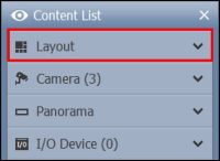
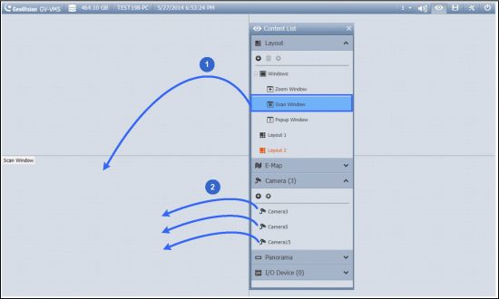
> Windows in the Content List and drag Scan Window to a live view grid.
18
* Live View
2.
Drag multiple cameras into the Scan Window.
3. Move the cursor to the Scan Window, click Tools and select Properties.
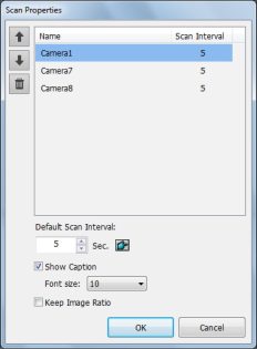
4.
To adjust the order of a camera, click Up 1 and Down *_.
19
![]()
You can designate a Popup Window to display live images of cameras, upon events, on a separate monitor. For this function to work, you must first create a live view layout on another monitor.
20
* Live View
Focus View
You can create up to 7 close-up views per camera and place these created close-up views inside live view grid. This function is not supported for Fisheye and PTZ Cameras.
appears.
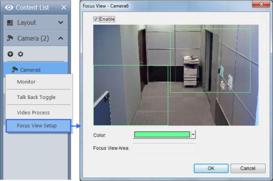
21
![]()
■ Double-Click: The camera will center on the spot you clicked.
■ Drag: You can select Random Move or Center Move after right-clicking the live view.
22
* Live View
® Random Move: Drag a line on the live view and the camera will move toward the direction you dragged.
® Center Move: Drag a box on the live view and the camera will zoom in on the area you dragged.
For details, see 1.11.1 Accessing PTZ Control Panel and Auto Functions, GV-VMS User Manual.
23
![]()
GV-VMS offers a number of video processing functions. To configure video processing functions, follow the steps below.
1.
> Video Process. This dialog box
Click Home > Toolbar £>3 > Configure
appears.
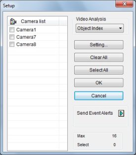
For details on event alert functions, see 3.21 Event Alert through E-mail Notification, GV- VMS User’s Manual.
24
5
Video Processing
The following Video Processing functions are only enabled when you start monitoring on the cameras.
If you have set an AVP schedule, Video Processing functions will be enabled according to the schedule regardless of monitoring. See 7.2 Setting up Schedules on how to set a schedule.
For details on video processing functions, see Chapter 3 Video Analysis, GV-VMS User’s Manual.
Chapter 6 Video Playback and Backup
25
![]()
Cameras
Ailcameras on Layout
12:54:17 o (g)
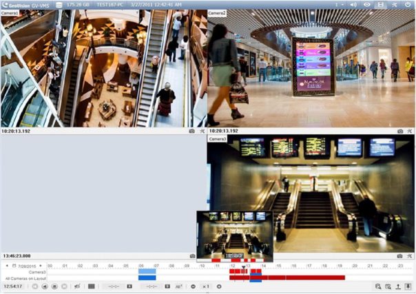
zoom in and out on the timeline.
• Blue areas: video recorded in round-the-clock mode and other alarm events.
• Red areas: videos recorded in motion, intrusion, IO event and other alarm events.
• Green areas: never recycle events.
• Yellow areas: video recordings retrieved form the SD cards of cameras when
reconnecting after a temporary disconnection.
• Turquoise areas (for V18.3.2 or later): video recorded in AI and PVD Motion events.
26
6
Video Playback and Backup
For details, see Chapter 4 Video Playback, GV-VMS User’s Manual.
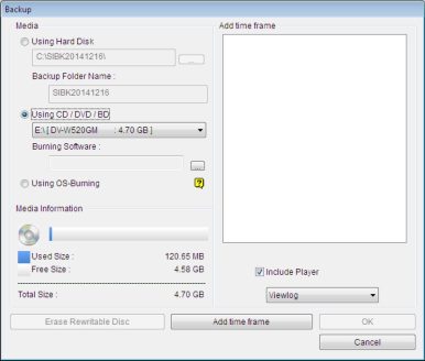
1.
In ViewLog, click Toolbar > Tools i—i > Backup. This dialog box appears.
27
![]()
Chapter 7 Other Important Features
1.
To set up I/O devices on GV-VMS, click Home > Toolbar > Configure w >
Accessories (if available) > I/O Device (if available) > I/O Device Setup.
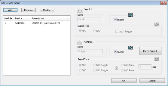
Note: The Accessories option only appears when GV-Keyboard or GV-Joystick has been set up on the GV-VMS. The I/O Device option only appears after at least one I/O device has been added.
28
2_ Other Important Features
4. After the I/O devices are added, select Toolbar > Configure > Accessories (if
available) > I/O Device > I/O Application Setup. This dialog box appears.
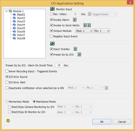
5. Select an input and specify the actions to take when the input is triggered.
Click OK to apply the settings.
To activate I/O functions, click Home > Toolbar > Monitor > I/O
Monitoring or Start All Monitoring.
For details on I/O setup, see Chapter 6 I/O Applications, GV-VMS User’s Manual.
29
![]()
You can create a schedule to enable and disable recording, video analysis, I/O monitoring, connection with Center V2 / Vital Sign Monitor / WebCam Server / Mobile Service / GV-Edge Manager and PTZ object tracking at specific times each day.
1. Click Home > Toolbar > Configure > Schedule Edit. This dialog box
appears.
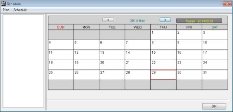
2. Click Schedule and select Setup Wizard. The Setup Wizard dialog box appears.
Tracking) and drag across the timeline to enable it during that time.

To set a recording schedule, click Camera, select a camera and click and drag on the desired time periods to specify how the camera is monitored throughout the day.
30
2_ Other Important Features

Tips:
31
![]()
GV-USB Dongle can be upgraded to include more functions or enhance the system. You need to collect the data from your dongle and send it back to GeoVision for an upgrade. The upgrade is charged services. To upgrade your dongle, follow these steps:
1. Each dongle has its own serial number. Find it on the side of the dongle. Later this serial number will be used in naming the files for upgrading.

2. Insert the dongle to the computer.
3. In the software folder, double-click GVUsbKeyUpClient.exe. This dialog box appears.
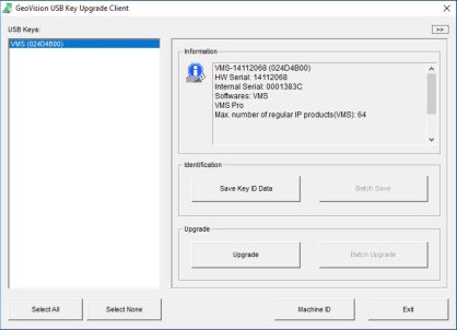
32
8
Dongle Upgrade
33
