9.2 Create Route file
You can create a Route file in FLIR Thermal Studio.
9.2.1 General
The Route file specifies the route structure, consisting of multiple levels of locations, assets, and inspection points. The Route file also specifies the statuses that can be set for an inspection point during the inspection and the configuration of the camera behavior.
You can build the route structure manually in FLIR Thermal Studio.
It is also possible to import a structure from an asset management system. The file to import must be an Excel file (.xslx) or a Comma Separated Values file (.csv). After the import, you can make additional changes to the structure and configure the Route file manually.
9.2.2 Create a Route file
1.Select the Routing tab, and then select the Routes view.
2.Groups:
To add a group at Level 1, click New group on the top toolbar.
Point at the group and then click the + button that appears. This displays a menu.
◦ Click New group to add a group at a level below this group.
◦ Click New asset to add an asset below this group.

3.Assets:
Point at the asset and then click the + button that appears. This adds an inspection point to the asset.

4.Groups, assets, and inspection points:
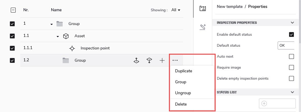
Point at the item and then click the buttons that appear.
◦ Click the Move up or Move down button to move the item.
◦ Click the three dots button. This displays a menu.
· Click Duplicate to duplicate this item and its dependents.
· Click Group to add a group at a level above this item.
· Click Ungroup to delete this group and move its dependents to the group above.
· Click Delete to delete the item and all of its dependents.

5.Enter the asset properties that will be displayed in the camera user interface as guidance to the operator:
In the center pane, click the item. This displays the item properties in the right pane.
◦ For all locations, assets, and inspection points, enter a Name in the properties pane.
◦ For the inspection points, you may want to add a Description, for example instructions or reminders.
6.Add reference image to an inspection point:
1.In the center pane, click the inspection point.
2.On the top left toolbar, click Show file explorer. This displays the library in the left pane.
3.Drag an image from the left pane and drop it on the Add image button in the right pane.
For more information, see section 9.4 Reference images .
1.Include asset check box:
Only clear the Include asset check box if you want to exclude the item when you export the route. You may, for example, want to create a Route file for only a part of the structure and then you clear the check box for the items you want to exclude.

2.Configure the settings that control the behavior of the camera during the inspection:
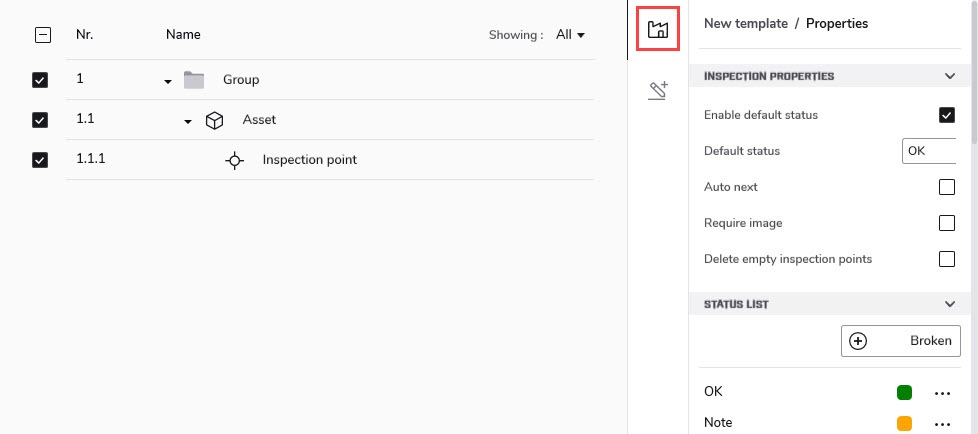
On the right pane toolbar, click the route properties button. This displays the route properties in the right pane.
◦ To change the default status, first select the Enable default status check box. Then click the Default status field and select a status from the menu that appears.
◦ Auto next: This setting defines if the camera after saving an image automatically will set the default status and step to the next inspection point. If most inspection points will have the default status, you will save inspection time by selecting the check box. If you often want to set the status or add comments to the inspection points, it may be more convenient to deselect the check box.
◦ Require image: This setting defines if the operator must save an image before it is possible to set the status of an inspection point.
◦ Delete empty assets: This setting defines if all empty inspection points (no image and no status) will be removed from the Inspection file when the inspection is finished.
◦ Status list: This setting defines the text and colors of the statuses. To add a status, first enter the name in the field, and then click the + button.

1.To save the Route file, click Save at the top right corner and save as a .routex file.
2.The Route file (.routex) is now ready to be used as template for inspections in the camera.
9.2.3 Import structure
1.Select the Routing tab, and then select the Routes view.
2.On the top left toolbar, click New route. This opens the route workspace screen.
3.On the top toolbar, click Import asset list.
4.In the Open window, open the file (.xlsx or .csv) from your asset management system.
5.In the Column mapping window, select how to map the columns in your file to fields in FLIR Thermal Studio.
6.When you have completed the mapping, click Import. This displays your structure in the route workspace.
8.To save the Route file, click Save at the top right corner and save as a .routex file.
9.3 Create inspection report
When you have completed an inspection in the camera, you can create an inspection report on the Routing tab in FLIR Thermal Studio.
9.3.1 Prepare inspection results
The inspection results, including all inspection data and images, are stored in the Inspection file (.route).
Make sure you have the Inspection file (.route) available on your computer.
9.3.1.1 Uploaded results
When uploading the inspection results to FLIR Ignite, the camera uploads the Inspection file (.route) to your FLIR Ignite account.
If FLIR Ignite Sync is set up for automatic sync, the Inspection file (.route) should be in your sync folder on the computer.
To manually transfer the Inspection file (.route) from FLIR Ignite to your computer, do the following:
1.Sign in to your FLIR Ignite account.
3.Select the .route file by clicking the row.
9.3.1.2 Results on memory card
To transfer the Inspection file (.route) from the camera memory card to your computer, do the following:
1.Connect the camera to the computer with a USB cable or insert the memory card into the computer.
2.Go to the folder named Inspections located at the root of the memory card.
3.Save the Inspection file (.route) to the computer.
Note In FLIR Thermal Studio, you can also open the Inspection file (.route) directly from the Inspections folder on the camera memory card.
9.3.2 Open inspection results
1.Start FLIR Thermal Studio.
2.Select the Routing tab, and then select the Inspections view.
3.On the top left toolbar, click Open inspection file.
4.In the Open window, find the location for the Inspection file (.route) and open the .route file.
5.To review the inspection results, click the inspection points one by one, or use the arrow buttons at the top of the right pane. The inspection image(s), reference image (if there is one),status, and any comments are available in the right pane.
You can edit the inspection images, change statuses, and add more information to the inspection points. To open the image editor, double-click the image.
6.Save changes:
◦ To save the changes in the original inspection file, click Save at the top right corner.
◦ To save the changes in a new file, click the button with three dots at the top right corner and then click Save as.
9.3.3 Create an inspection report
2.On the top left toolbar, click Generate inspection report. This opens the Available templates window.
3.In the Available templates window, click a template and then click Select.
◦ Inspection default template: Template for inspection reports (with this template, the reference images will not be included in the report).
4.The report workspace screen opens. You can make additional changes to the report using the normal reporting functions.
5.You can save the report as an .atr file. This will allow you to continue working with the report later. At the top right corner, click the button with three dots and then click Save as report.
6.You can export the report to, for example, a PDF file. At the top right corner, click the button with three dots and then click Export to PDF.
9.4 Reference images
Reference images enable guidance support, increase quality in decision making in the field, and speeds up data collection by defining a baseline for the user based on a set of predefined parameters.
With FLIR Thermal Studio, it is possible to convert the images from an inspection to reference images. You can also add reference images manually when you create a Route file.
The camera can be configured to use the same measurement tools, measurement parameters, temperature scale values, and color palette as in the reference images.
9.4.1 Create Route file with reference images from inspection
You can export an inspection to a Route file (.routex) and use the inspection images as reference images in the new Route file.
Note Do not add any reference images at this point. It is only possible to have one reference image for each inspection point. If there already is a reference image in the Route file, it will not be possible to replace it with an inspection image.
2.Perform an inspection with the camera and take reference images for all inspection points.
4.Start FLIR Thermal Studio.
5.Select the Routing tab, and then select the Inspections view.
6.On the top left toolbar, click Open inspection file and open the Inspection file (.route).
7.On the top left toolbar, click Export to new route.
8.When asked, click Yes to save the inspection images as reference images.
9.For inspection points with more than one image, select the image you want to use as reference image. Then click Export.
9.4.2 Add reference images manually
You can manually add reference images to a Route file in FLIR Thermal Studio.
1.Select the Routing tab. Do one of the following:
◦ Import an existing Route file: On the top toolbar, click Import route and open a Route file (.routex).
2.In the center pane, click the inspection point.
3.On the top left toolbar, click Show file explorer. This displays the library in the left pane.
4.Drag an image from the left pane and drop it on the Add image button in the right pane.

5.To delete the reference image, click the Clear reference image button in the right pane.
To edit the reference image, double-click the image. This opens the image editor.
9.4.3 Report with reference images
With the Inspection default ref image template, the reference images will be included in the report.
You can also add reference images to your own report templates. For details on how to add elements, see chapter 7 Edit reports .
To add reference images to a report template, do the following:
1.Select the Reporting tab, and then select the Templates view.
2.Right-click the template you want to use, and then click Edit.
3.In the page pane, click the report page where you want to add the reference image.
4.On the top left toolbar, click Add page element. This displays the available elements in the left pane.
5.In the elements pane, click Thermogram. A placeholder for a thermal image is added to the report page.
6.In the right pane, scroll down to the Tag field and enter reference_image .
You may also want to add a Text box with information that this is a Reference image.

Batch processing
This chapter describes the Batch edit tab and how you create and run batches of jobs.
10.1 General
Use the batch processing feature for automation of repetitive tasks when editing and normalizing thermal images. Operations that can be automated are, for example:
When processing batches of jobs, the following outputs are available:
• Radiometric images (.jpeg) for further processing.
• Plain overlay images for sharing online or with customers.
• Transcoder from a radiometric sequence to an AVI video file.
• Radiometric data exported to CSV files.
Batch jobs are saved in the .atb (advanced thermal batch) file format.
10.2 Navigation
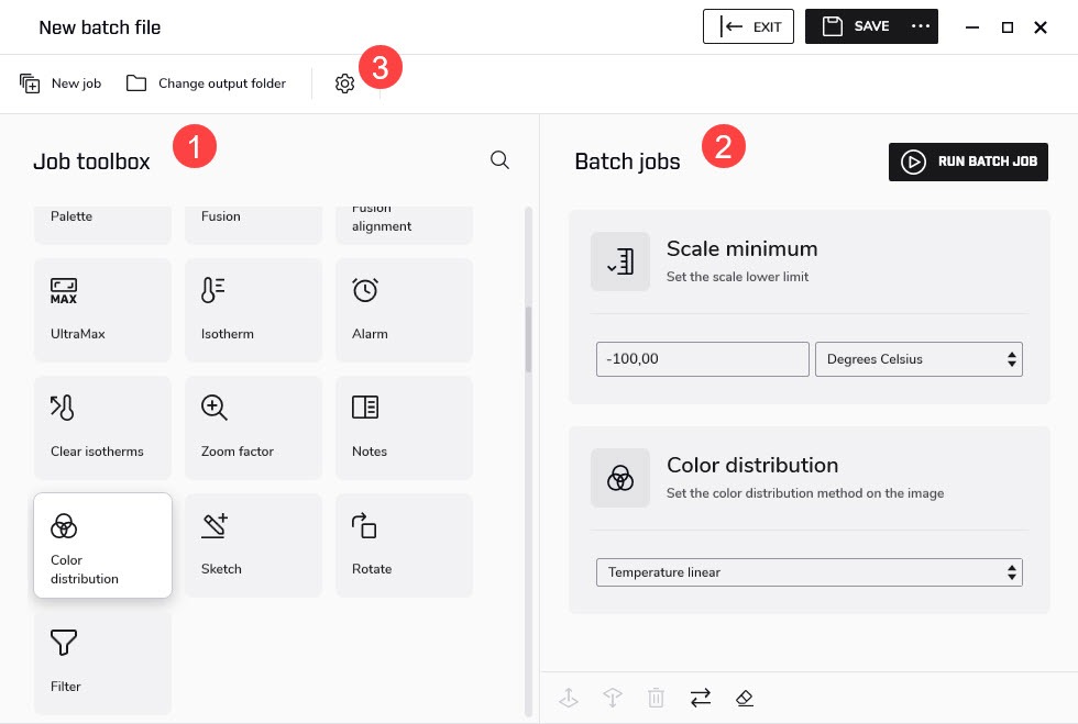
This image shows what the user interface looks like when working with a batch.

1.Job toolbox pane
The toolbox lists all the jobs that can be run in a batch. The jobs are grouped into categories, such as the Output targets, Image, and Parameters categories.
2.Batch jobs pane
This is the workspace where you create the batch by adding jobs and setting values. As more jobs are added, a batch execution list is created.
A new job is normally added at the end of list. Use the icons at the bottom of the pane to move the jobs up or down the list, to reverse the execution order of the jobs, to remove jobs from the list, or to clear the list of all jobs.
3.Click the icon to open the Settings window.
General tab: If the Open output folder when done check box is selected, File Explorer will open when the batch job is completed and show the output files in the defined output folder.
Image Overlay tab: Configure if and how you want to use an image overlay for batch processing. For more information, see section 4.2.5 Image Overlay .
10.3 Start a new batch
1.Select the Batch edit tab.
2.On the top toolbar, click New job. This opens the batch workspace screen.
3.In the Job toolbox pane, click the jobs you want to add to the batch. Point to a job to see a short description. The jobs are added to the Batch jobs pane.
4.Note that some jobs have additional settings. In the Batch jobs pane, make any changes to the job settings.
5.Use the icons at the bottom of the pane to:
◦ Move a selected job up or down the list.
◦ Remove a selected job from the list.
◦ Reverse the order of the selected jobs.
◦ Remove all jobs and clear the list.
6.Verify that you have added an Output target job as the last job in the batch.
Note At least one Output target job must be run in the batch. If no output target has been selected, the job Radiometric JPEG will be added automatically and run as the last job in the batch.
7.To run the batch job, click Run batch job at the top of the right pane. This opens the image workspace screen.
8.In the left pane, select images and/or folders and drag-and-drop them into the right pane.
9.Use the icons at the bottom of the right pane to:
◦ Move a selected file up or down the list.
◦ Remove a selected file from the list.
◦ Sort the files by name, or by date and time.
◦ Reverse the order of the selected files.
◦ Remove all files and clear the list.
10.To change the output folder, click Change output folder at the top toolbar.
11.To start the processing, click Run batch job at the top toolbar.
12.When the processing is completed, click Go to output at the top toolbar. This opens the output folder in the left pane.
13.To take a closer look at a result file and edit it if necessary, double-click the file in the left pane. This opens the image in the image editor. For more information, see 5 Image editor .
10.4 Save a batch as a template
1.Select the Batch edit tab.
2.On the top toolbar, click New job. This opens the batch workspace screen.
3.Select which jobs to run, set values where applicable, and place the jobs in the correct order. See also section 10.3 Start a new batch .
4.To save the batch as a template, click Save at the top right corner.
10.5 Start a predefined or saved batch
1.Select the Batch edit tab.
2.In the left pane, click the batch you want to run.
3.In the right pane, click Run job. This opens the image workspace screen.
4.Select the images to be processed and place them in the correct order. See also section 10.3 Start a new batch .
5.To start the processing, click Run batch job at the top toolbar.
10.6 Create a panoramic image
Use the Panorama functionality to stitch a sequence of thermal images together into one single panoramic image.
Note
• The sequence of image files used as input must come from the same recording.
• The order of the image files in the sequence is not important.
• Only one panoramic image can be created at a time. If you select image files from multiple sequences as input, only the images of the first selected sequence will be processed.
To create a panoramic image, follow this procedure:
1.Select the Batch edit tab.
2.In the left pane, click Panorama.
3.In the right pane, click Run job. This opens the image workspace screen.
4.In the left pane, select a folder or individual images and drag-and-drop them into the right pane.
5.To start the processing, click Run batch job at the top toolbar.
6.When the processing is completed, click Go to output at the top toolbar. This opens the output folder in the left pane.
7.Optionally: Double-click the panoramic image in the left pane. This opens the image editor where you can change zoom, change palette, crop, or rotate the panoramic image.
Live stream
This chapter describes how to live stream, record radiometric video, and control USB connected cameras.
11.1 Connect camera
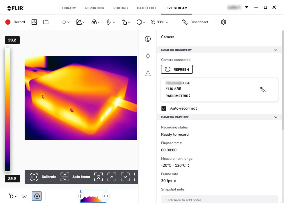
1.On the computer, start FLIR Thermal Studio and select the Live stream tab.
3.Connect the camera to the computer with a USB cable. This displays the Device connected dialog.
4.In the Device connected dialog, you can select to import all files, download all inspections, or view all files.
5.On the Live stream tab, select the camera and then click Connect. This displays the live image stream from the camera.
Note
◦ Click Refresh to update the camera list.
◦ If you select the Auto-reconnect check box, the camera will connect automatically next time.


