HIP2P Client Setup Manual,HiP2P Software is a CMS which helps us to connect and control the Dericam CCTV cameras. This is designed and developed by the Shenzhen Dericam Technology Company.
Hardware environment:
- > Pentium IV series, CPU frequency above 2.0G
2> 2G or more memory
3 > Hard disk 120G or higher
4> Display resolution of 1024 x 768 or higher
HIP2P Client Setup Manual
Read More :
Software environment:
Windows2000 / WindowsXP / Windows2003 / WindowsVista / Windows 7/8/10, Windows XP is recommended.
Double-click the installation package, the following interface pops up:
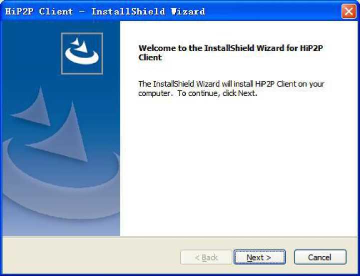
After selecting the installation path, click “Next” to complete the installation.
After installation, the following icon will be displayed on the desktop:

 The following interface is displayed in the program bar:
$ help
* HiF2F Client
2 Uninstall
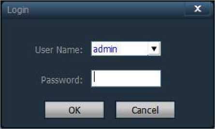
[Login] When login, the default user is admin, password is blank. Click the “Confirm” button
directly to enter the main interface of the CMS client.
[Exit] Only users with admin permissions can exit the CMS client, users with user and guest permissions cannot exit the CMS client.
When exiting the CMS client, you need to enter the user name and login password with administrator permissions to exit the client
![]()
![]()
![]()

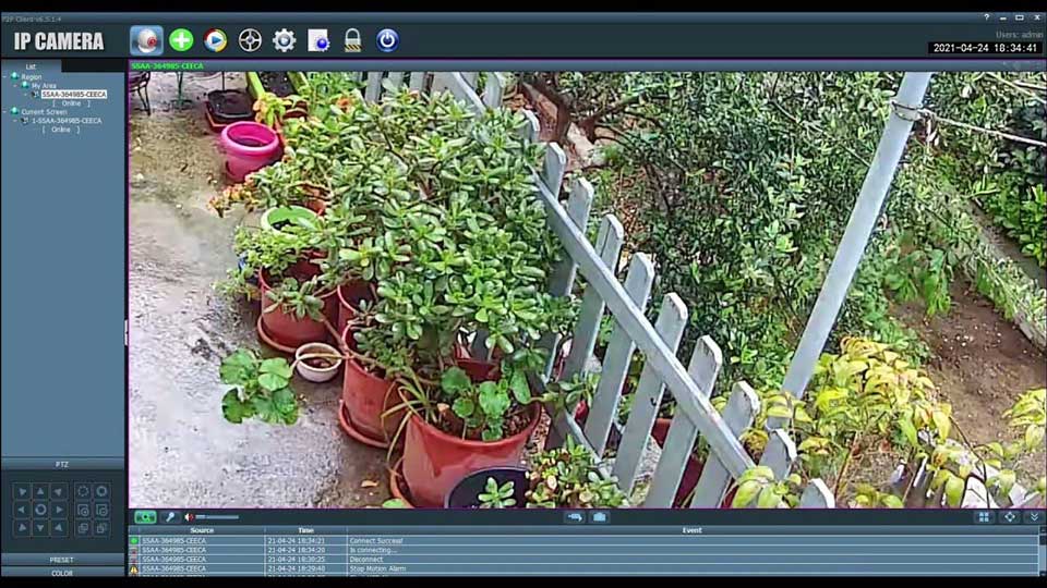
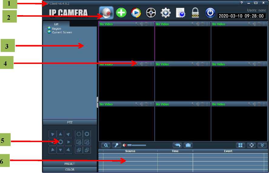
The software interface is shown in the figure above, mainly divided into 6 large blocks:
1 System button bar 2 Tab bar
3 Device tree
4 Real-time preview 5 PTZ Control
6 Alarm information list
♦System button bar:
Help button, click to open client instructions
Hide button, click to hide the software into the system tray
Maximize button, the software covers the entire screen after clicking
Exit button, click the software to pop up the exit prompt
♦Tab bar:
IP CAMERA
LOGO information
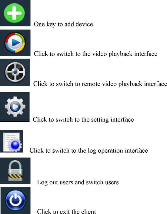
Click to switch to the image preview interface
♦Device tree:
[List mode] User-configured list level to display areas, settings, and channels
[Current screen] Display the devices connected to the current screen, only in list mode
![]() ♦Real-time preview:
♦Real-time preview:
Electronic zoom button, click to draw an area on the screen with the mouse, then the area
![]() can be enlarged
can be enlarged
Voice intercom button, select the window that needs to open the intercom and click the
intercom button, the status bar of the window will display , you can implement voice
intercom, only one device of voice intercom can be opened at the same time
Sound monitoring button, click to open sound monitoring, the status bar of the window
![]()
will display
, click again to turn off sound monitoring, you can turn on sound
monitoring for multiple devices at the same time
Record button. After selecting the window to be recorded, click the record button to start
manual recording. The window status bar will display
. Click again to close the
manual recording
![]()
![]() Picture snapshot button. After selecting the window to snapshot the picture, click the snapshot button to achieve picture snapshot. If you click the snapshot button continuously, you can snapshot max 2 pictures in 1 second.
Picture snapshot button. After selecting the window to snapshot the picture, click the snapshot button to achieve picture snapshot. If you click the snapshot button continuously, you can snapshot max 2 pictures in 1 second.
Multi-screen selection button, click to select multi-screen image display, select 1, 4, 6, 8, 9, 16 screens
Full screen display button, real-time preview area can be displayed in full screen after
clicking
Alarm information list shrink or expand button, click the alarm information list to shrink,
re-click the alarm information list to expand.
Before using the client software, you need to add and configure the device. Click the “Setting” button in the tab bar to enter the device management page.
[Add list tree]
♦ The software runs initially, the list tree is empty by default. Click the “Add Area” button to pop up the “Add Area” dialog box. Fill in the name in the area name field and click OK to add an area to the list tree. Because the area added this time is the first area, the area does not exist
belonging area, that is, the belonging area is empty.
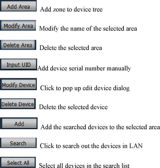
 Note: The list tree can add max 128 regions at present.
[Add device]
♦Search and add devices in LAN:
![]() Click the search button,the client will search out all the devices in the LAN at this time, then select the devices to be added in the search list. After selecting the area, click the button
Click the search button,the client will search out all the devices in the LAN at this time, then select the devices to be added in the search list. After selecting the area, click the button
to add the device, it can add the selected device to the area.
♦ Add devices manually:
Click the button
to pop up a dialog box for adding a device, as shown below:
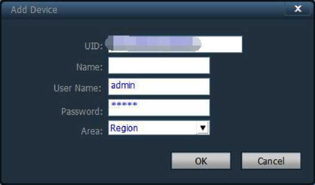
[UID] Device UID code, each device has a different UID code
[Name] The name of the device can be self-defined. The device name can be entered
max 15 Chinese characters. (Note: After entering the name, only the name of the device is displayed on the device tree in the preview window, not display the UID of the device)
[User name] User name of the device, default is admin
[Password] password of the device, default is admin
[Area] display area of the device
Fill in the required information and click the OK button to complete the device addition.
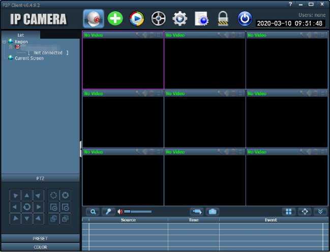
After configuring the device, click the “Preview” tab in the tab bar to return to the monitoring main interface. The device tree is displayed as a list tree by default. Click “Group” and “List” on the device tree to switch between group and list information.
The display screen defaults to 4 screen division display, and supports maximum 36 screen divisions.
The maximum screen division is optional. There are three screen modes of 16/25/36.The higher the screen, the higher the performance of the host required. The 25 or 36 screen display is
![]()
![]()
![]()
recommended to use an i3 CPU or more and an independent graphics card.
Display screen description:
It indicates that there is no device connected to this channel. If connected, the OSD
information of the device will be displayed
Intercom status, when the icon changes to
indicate that the channel is intercoming,
otherwise the channel is not open intercom;
![]()
![]()
Monitoring status. When the icon changes to
indicate that the channel is monitoring,
otherwise the channel is not enabled for monitoring;
![]()
Recording status. When the icon changes to
indicate that the channel is manually
![]()
recording; when the icon changes to
indicate that the channel is plan record;
Double-click the device UID or name in list mode, or drag the UID to the window to display the
![]()
image. (When the device is not connected, the offline status is displayed)
After the device is connected, a blue triangle
ujJ ,s
displayed on the UID or name.
If displayed ‘ on the
device, means the device is not connected. If
displayed
on the device, means the channel is recording.
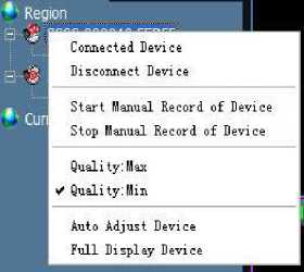
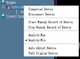
Right-click on any area and it will pop up as shown on the right:
[Connect all] Connect the device in the selected area
[Start area manual recording] Enable manual recording of the device in the selected area [Stop area manual recording] Stop manual recording of the device in the selected area [Picture quality]Choose different picture quality according to different network environments:
HD and SD
[All Auto-adjust screens]The selected area device adjusts the screen display ratio automatically
[All Full screen display] The selected area device displays the image according to the size of the split screen
Note: After the image stopped display, the device is still connected. If the device has started the recording function, the device will still keep recording after stopping the display.
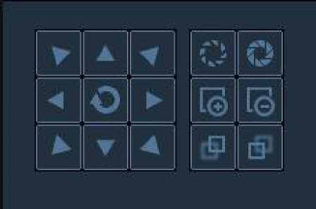
You can control the 8 directions of the PTZ by using the direction keys; select the speed of the PTZ by dragging the slider. “-” indicates that the rotation speed of the PTZ is slower, and “+” indicates that the rotation speed of the PTZ is faster.



![]()
Aperture zoom in button, requires lens support to be effective
Aperture zoom out button, requires lens support to be effective
Focus bigger button, requires lens support to be effective
Focus smaller button, requires lens support to be effective
Focus forward button, requires lens support to be effective
Focus backward button, requires lens support to be effective
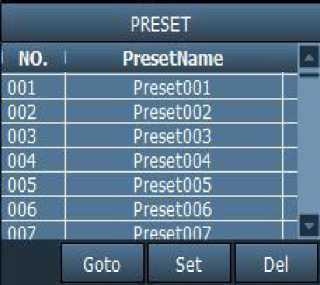
The client supports maximum 256 presets.
For details on how many presets can be used, please refer to the description of the number
of presets supported by the camera.
[Preset setting] Select the window that needs to
set the preset point, then select the preset point
number, and click the “Preset” button, then the preset
point is set successfully.
[Preset call]Select the window needed to call the preset point, then select the preset point number, and click the “call” button. You must set the preset point before selecting the call.
[Preset delete] Select the window needed to delete the preset point, then select the preset point to be deleted, and click the “Delete” button, then the preset point is deleted successfully.
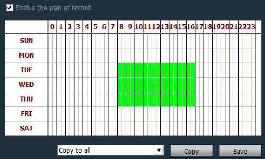
Select “Settings”-“Recording Management”-“Enable Scheduled Recording” in the tab bar as shown above:
SUN to SAT represents a week, in days; 0 to 23 represents a day, in half an hour.
[Enable plan record] Select the channel, and click the left mouse button to drag a green block in the schedule table, as shown in the figure above; the range of the green block is the time period for starting the scheduled recording. After setting the time period, click Save.
[Close plan record] Tick to cancel the enable plan record and click Save; or cancel the green block in the schedule list and click Save. The method of cancel the green block: Just click the left mouse button on the green block and drag the mouse to cancel the green block.
Note: If the plan record time is the same for all devices, just set one device and click Copy and Save, then all devices enabled plan record.

[ Common record length ] The size of a single record file: the system sets the video length to 5 minutes by default. The length of a single video file can be set to 1-30 minutes. If you want to modify the video duration, please modify and save in the normal record length.
[ Alarm duration ] You can set the length of alarm recording, the default is 10 seconds, 5-60 seconds can be set.
[The remaining disk starts to reclaim space] The selectable range is 1G ~ 50G. When the disk space is less than the set range, start to skip to another disk for recording or delete the earliest day’s recording file (the default recovery is 20GB)
[Record type] 264/265 and AVI two record types. When the video type is 264, the playback tool must use the manufacturer’s player to playback the video.
[Full disk overwrite recording]Select “Yes”, when the space of all disks is less than the set disk space, delete the earliest recorded files. Select “No” to stop recording when the space of all drive letters on the disk is less than the set disk space
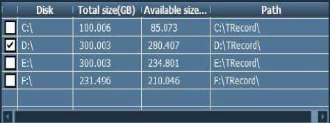
[Recording path]After the client is installed, the client software detects the hard disk of the machine automatically and displays it in the list. The default recording is to D drive.
![]()
Select the window, click the button
or right-click the window to select the recording. For
the duration and path settings of the recording, please see the plan record.
Note: 1. The client supports maximum 24 drive letters, that is, the memory can connect up to 24 hard disks.
2.The icon i. on the screen indicates that the channel is planning to record; the icon
LJ
on the screen indicates that the channel is manually recording.
![]() Video playback button, click this button to continue playback after the video playback finished
Video playback button, click this button to continue playback after the video playback finished
Stop playback button, click this button to stop playback during video playback
![]() Single-frame playback button. Click this button during video playback to perform
Single-frame playback button. Click this button during video playback to perform
single-frame playback. Each click plays a frame of image screen.
Image snapshot button, click this button after selecting the playback window to save the picture to disk
![]() Electronic zoom button, select this button during video playback, and then draw the area of the enlarged image in the window
Electronic zoom button, select this button during video playback, and then draw the area of the enlarged image in the window
![]() Full screen button. Select this button to display the image window area in full screen. For a single window full screen, double-click the corresponding window.
Full screen button. Select this button to display the image window area in full screen. For a single window full screen, double-click the corresponding window.
![]() During the video playback process, select the playback speed to play through the drop-down box. Default is normal speed playback.
During the video playback process, select the playback speed to play through the drop-down box. Default is normal speed playback.
s Sound button, you can choose whether to turn on the sound during the video playback, the sound is turned off by default.
[Video playback search]
Step 1: Select the video file type and search time
Step 2: Select the window to be played back, select the device channel to be played back in the list tree.
Step 3: If there are eligible video files in the selected time range, they will be displayed on the timeline panel.
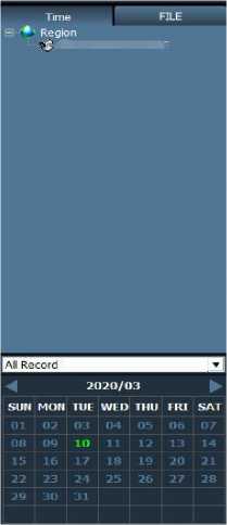 Step 4: Double-click the device channel for video playback.
Step 1: Select the video file type and device channel
Step 2: Select the search time and click the “Search” button, the system will display the qualified video files in the device tree;
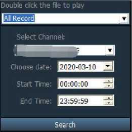 Step 3: Select the playback window and double-click the video file to playback the video file. Playback supports the same video file in four windows at the same time;
You can remote playback the timed recording or alarm recording in the SD card, select the playback channel, date, start and end time; then click Search can playback the recordings in the SD card(remote playback requires the device is connected, if not connected, click search button, it will prompt the device is not connected);
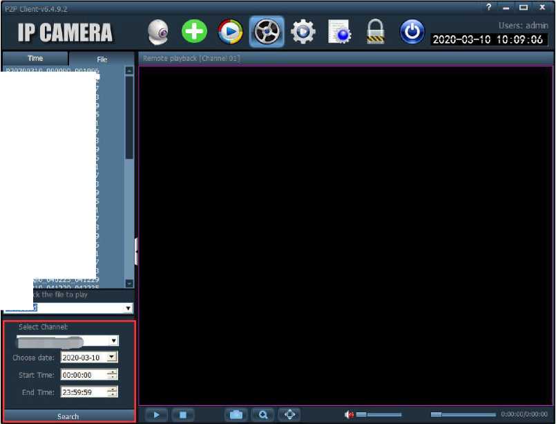 P2020U310_U0UU0U_U01U0b P20200310_001006_002012 P20200310_002012_003017 P20200310_003017_004023 P20200310_004023_005029 P20200310_005029_010035 P20200310_010035_011041 P20200310_011041_012047 P20200310_012047_013053 P20200310.013053.014059 P20200310_014059_015105 P20200310-015105-020111 P20200310_020111_021117 P20200310.021117_022123 P20200310.022123.023129 P20200310—023129_024135 P20200310—024135—025141 P20200310—025141—030147 P20200310—030147—031153 P20200310.031153.032159 P20200310—032159.033205 P20200310—033205—034211 P20200310—034211.035217 P20200310.035217-040223 P20200310 040223 041229
Double
|All Record
After searching out the remote video file, right-click on the video file to be downloaded, the download file button will appear, click to pop-up download interface, click Start, and the video file will start download.
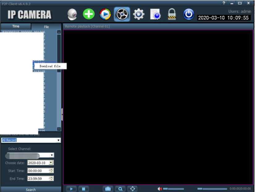 P2O2OO31O_000000,001006 P20200310.001006,002012 P20200310_002012_003017 P20200310.003017.004023 P20200310_004023_005029 P20200310_005029_010035 P20200310.010035.011041 P20200310.011041,012047 P20200310_012047.
P20200310_013053.
P20200310.014059.015105 P20200310_015105,020111 P20200310-020111,021117 P20200310-021117,022123 P20200310.022123 023129 P20200310,023129,024135 P20200310.024135.025141 P20200310_025141_030147 P20200310-030147-031153 P20200310.031153,032159 P20200310_032159,033205 P20200310-033205,034211 P20200310-034211.035217 P20200310.035217,040223 P20200310,040223,041229
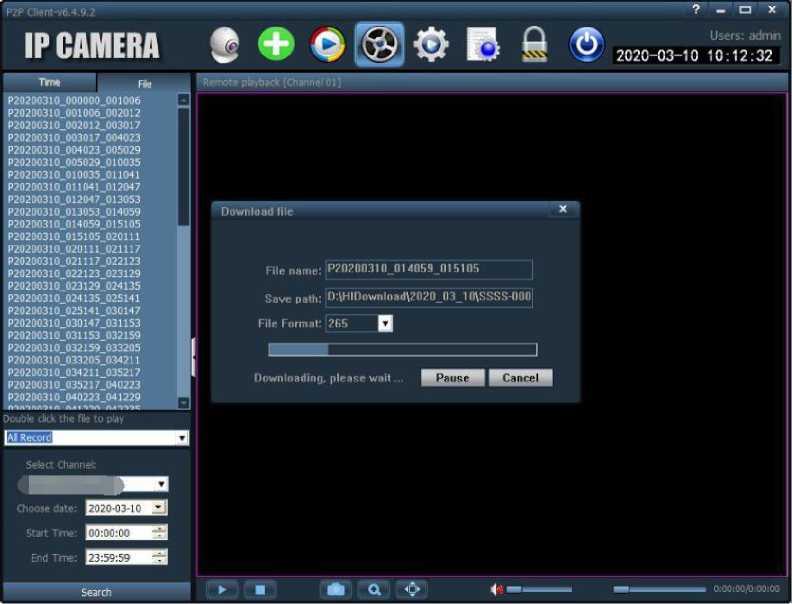 Double cbck the file to play
Before modifying device parameters, please connect
related devices, as shown on the right:
Connect the device
- Video encoding: frequency and video encoding can be set;
- Video parameters: video resolution, code stream type, bit rate, frame rate, main frame interval, video encoding control and encoding quality can be set;
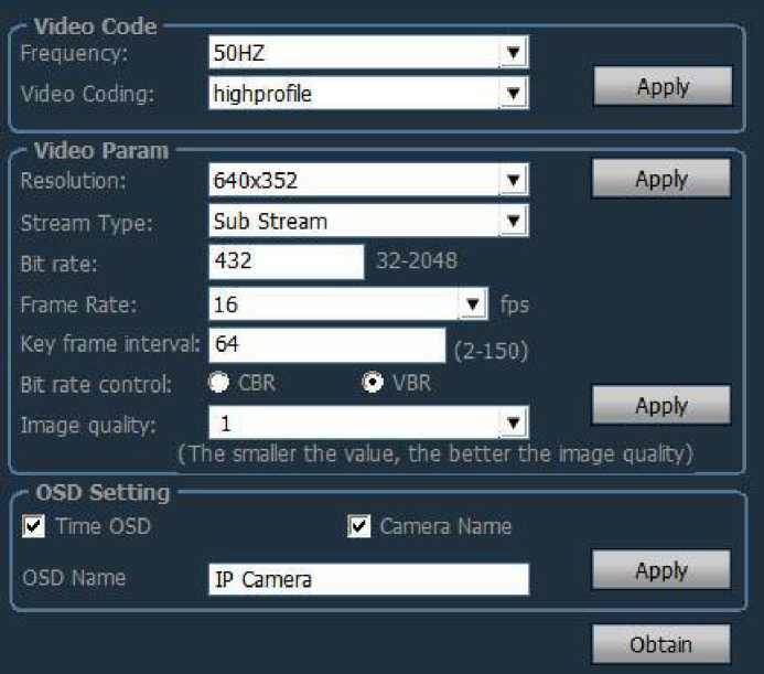 OSD settings: You can set the overlay name and overlay time;
Note: If the device is connected to high-definition, the resolution is the resolution of the main stream; if the device is connected to SD, the resolution is the resolution of the sub stream;
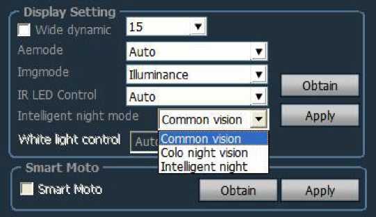
- WDR: Check the box in front of WDR, it indicates that WDR is on. WDR level is 1-30 optional
- Exposure mode: can set three modes: auto, indoor, outdoor. Default is auto mode.
- Image priority mode: You can set priority of illumination and frame rate;
- Infrared light control: can be set to auto, on, off. Select on is black and white mode; select
off is color mode.
- Intelligent night vision mode: you can choose common night vision, full color night vision and intelligent night vision (requires camera support)
- Intelligent tracking: only cameras with this function can be used
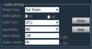
- Stream type: main stream and secondary stream optional;
- Capture audio: on or off
- Audio format: G.711 or G.726 optional
- Audio input: microphone input, linear input optional
When the audio input is microphone input, the input volume and output volume are 80 and 95, respectively.
When the audio input is linear input, the input volume and output volume are 10 and 95.
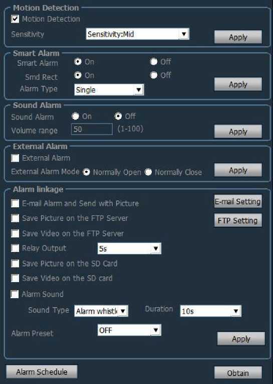
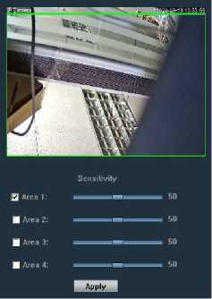
- Motion detection
You can turn on and off the motion detection function: ticking in front of motion detection indicates that motion detection is enabled, and not ticking indicates that motion detection is not enabled;
Sensitivity: sensitivity selectable: low, medium, high; low sensitivity is 25; medium sensitivity is 50; high sensitivity is 75
- Intelligent human shape recognition
The device that support human shape recognition can choose to enable or disable the human shape recognition function, and select the linkage mode, etc.
- Sound alarm
Can set sound alarm on and off; set the volume range, 1-100 can be set, the default is 50;
Note: This function only apply to some models;
♦ External alarm
Can set to open the external alarm ON and OFF; only support the devices with alarm input and
output;
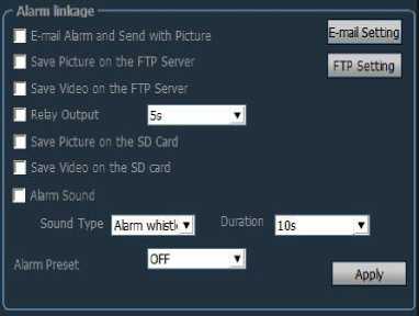 Alarm linkage
Can set
- Email alarm and send alarm picture;
- Save picture to FTP server;
- Save video to FTP server;
- Relay output
- Save picture to SD card;
❖ Save video to SD card;
❖ Alarm sound
❖ Alarm preset
♦ Email set
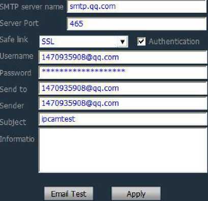 Sender mailbox take QQ mailbox as an example:
E-mail Setting X
Smtp server: smtp.qq.com
Server port: 465
Secure connection:SSL
Username and password fill in QQ account and password
Receiving address: Email address to receive alarm pictures
Sending address: sender’s email address, here take QQ mailbox as an example, you need to fill in the QQ email address; (same as filled user name)
Subjects and information can be filled in casually;
After filling in, click the setting button;
♦ FTP setting
FTP setting:
FTP server: Fill in the erected FTP address;
server port: Fill in the FTP port;
Username and Password fill in the username and password
set in the FTP server
Create directory automatically: If selected, the directory will
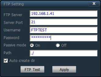 be created automatically. The directory name is today’s date.
♦ Alarm time setting
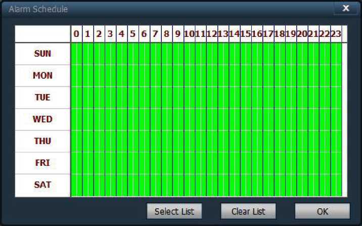
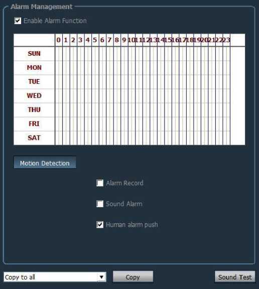
SUN to SAT represents a week, in days; 0 to 23 represents a day, in half an hour.
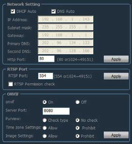
Please configure the network parameters according to the actual situation. No matter the device is set to manually set IP or obtain IP through DHCP, the client only displays the IP of the current device.
- RTSP port
Set RTSP port and select RTSP permission check
- ONVIF
Set ONVIF related parameters;
ONVIF ON and OFF, ONVIF port, time and time zone settings, image parameter settings, etc .;
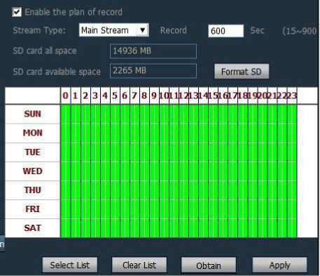
Enable plan record: enable timed recording;
Stream type: video streams have main stream and sub stream optional;
Video length: 15 seconds-900 seconds can be set, the default is 600 seconds;
Format SD card: can format SD card
Recording time can be set; the right picture shows green is the recording time;
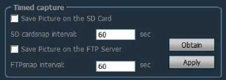
Ticking “Save pictures to SD card”, when the SD card time interval is 60 seconds, it means that every 60 seconds, a picture is captured and saved to the SD card.
Ticking “Save pictures to FTP server”, when the FTP interval is 60 seconds, it means that every 60 seconds, a picture is captured and saved to the specified FTP server.
Can set PTZ protocol, baud rate, data bit, stop bit and other information
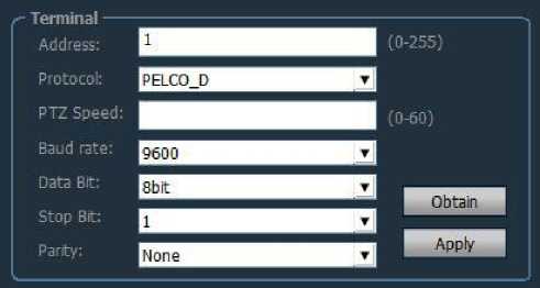
Note: The PTZ setting function only apply to some models;

Can modify password of the device
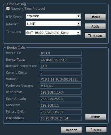
Set NTP server, synchronization interval, time zone, etc.
- Device information
Can obtain the current information of the device; including the device name, software version, IP address, MAC address, etc .; can restart the device and restore factory settings
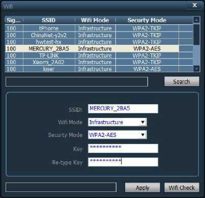
The steps to set WIFI:
Step 1: Click on the wireless connection and click search WIFI signal
Step 2: Double-click the SSID of the WIFI you are using.
Step 3: Enter the WIFI password key
Step 4: Click the setting button, then click the WIFI detection button, after prompted setting successfully,
finally unplug the network cable of the device.
Can set the area of motion detection for the camera
Select the camera to be set, enable the alarm linkage; select the time of the alarm linkage, you can set the alarm linkage recording and sound alarm; select the human shade alarm push, when the
camera is humanoid alarm, the client will push the humanoid alarm prompt
The factory default administrator user name is admin and the password is blank. After logging in, the administrator can add users, delete users, and set user permissions. User permissions are: admin, user, guest.
Admin permissions: can perform device management, user management, video monitoring, video playback, map settings, log query, switch users and exit client
User permissions: video monitoring, video playback, map settings, log viewing, user switching, and password change
Guest permissions: Video monitoring, user switching and password change.
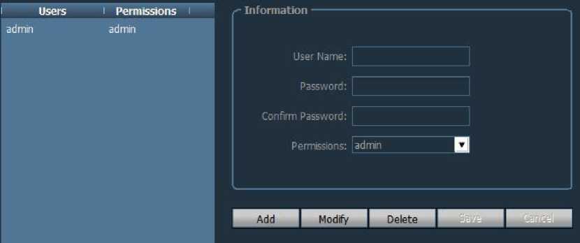
Step 1: After logging in with a user of admin permission, select “Settings”-“User Management” in the tab bar
Step 2: Click the “Add” button, enter the username and password, and select the user’s permissions
Step 3: Click the “Save” button, the user is added successfully
Step 1: After logging in with a user of admin permissions, select “Settings”-“User Management” in the tab bar
Step 2: Select the deleted user and click the “Delete” button
Step 1: After logging in with a user of admin permissions, select “Settings”-“User Management” in the tab bar
Step 2: Select the user and click the “Edit” button
Step 3: Select user permissions and click the “Save” button
Step 1: Select “Settings”-“User Management” in the tab bar
Step 2: Select the user and click the “Edit” button
Step 3: Enter the new password and click the “Save” button

Log type:
[All logs] Record all system information
[System log]Record user login, logout, and user matching information
[Operation log] Record all operation information of the user
[Alarm log] Record alarm information of the device
Step 1: Select “Settings”-“Other Settings” in the tab bar
Step 2: Select the time in the log save time, the save time have: one month, two months, three months, six months, and click the “Save” button
Step 1: Select the log type and sub-log type
Step 2: Select the device for viewing logs. The default is all devices.
Step 3: Select the start time and end time of the query log and click the “Search” button
Step 1: Select the log type and sub-log type
Step 2: Select the device for viewing logs. The default is all devices.
Step 3: Select the start time and end time of the query log and click the “Search” button
Step 4: Click the “Export” button and select the backup path
Note: 1. When backing up the log, you must search the log before backing up
- .The exported log format is Excel format
- . If the number of exported logs exceeds 5000, only 5000 records will be saved in each Excel table, and the excess will be converted into another Excel table, and so on.
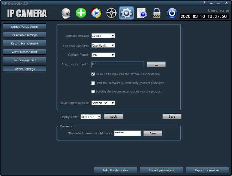
[Connection timeout] connection timeout can be set to 5-60 seconds
[Log save time] There are four options: one month, two months, three months, and six months.
The logs in the CMS client will not be deleted within the set time.
[Snapshot format]Refers to the image format captured by the client. There are two formats: JPG and BMP.
[Image snapshot path]Refers to the path where the client snapshots the picture
[System boot to run program automatically]Start WINDOWS to load monitoring software automatically, if not selected, it will not start.
[Number of single screens]can set the maximum number of single screens: 16 screens, 25 screens, 36 screens (requires restarting the software to take effect)
[Display mode]Drect Draw means flat rendering; Drect 3D means 3D rendering
[Password]Can set the default password when adding a device
[Save]Modify the parameters need to click the “Save” button for the settings to take effect
[Export parameter]Export all setting parameters of the client (back up all configuration parameters)
[Import parameter]Import the exported setting parameters to another client and restore all the configuration parameters (the two client versions must be the same, if they are inconsistent, an exception may occur)
[Rebuild video index]Delete the recording database index file and re-establish the recording database index file
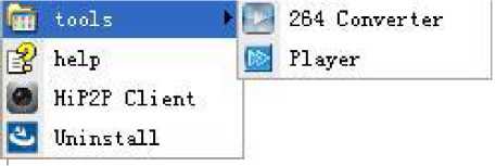
Enter the program bar and open “264 Converter”
The following interface appears:
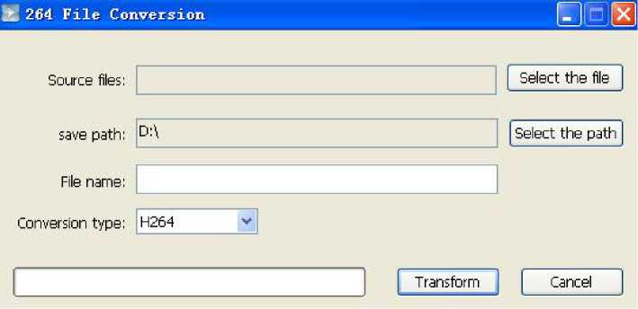
The steps are as follows:
- Select the file: select the video file to be converted;
- Select the path: set the save path after conversion;
- File name: the file name after conversion;
- Conversion type: the type of file to be converted (including H.264 AVI and ASF); After setting the above, click “Transform” to convert;
