Huawei Cluebase VMS User Manual, by vCloud.ai is new-generation Video Management Software that works on MacBook, Windows, Linux and even Web browser of literally any device. vCloud.ai Cluebase VMS is made for reliability, performance, and convenience. Flexibility and limitlessness by design allows creating advanced computer vision systems in a very short time. The vCloud.ai API allows integrating third-party hardware and software to extend your video system’s functionality even further. The advanced ergonomic interface makes all functions intuitively easy to use.
Cluebase VMS by vCloud.ai User manual
Purpose of the VMS
Cluebase VMS (video management system) is a software product that allows connecting video cameras to the server for further recording, live view and multiple additional functions.
Cluebase VMS is distributed as an open-platform commercial product under End User License Agreement.
System description
Cluebase VMS consists of the following parts:
2.1. Front-end (Web/Lunix/MacOs/Windows)
2.2. Back-end: server-side application that runs in the background
Cameras connect to Cluebase VMS via ONVIF and RTSP protocols.
Users can connect to the cloud unlimited number of cameras individually and set individual recording plans on them.
Hardware requirements
Minimal server requirements: Dual-core ARM or Intel/AMD (32 or 64 bit), 2GB RAM, 2GB HDD/SSD. Desktop client requires a PC or Mac computer with Intel/AMD 32 or 64 bit, Apple Silicon or other ARM CPU with at least 2 cores of 1.5 GHz each. Supported browsers: Google Chrome v.92+, Mozilla Firefox v.90+, Safari v.14+
Compatibility
4.1. Codecs: Cluebase VMS is ready to work with any h.264 video stream though h.265 is supported with limited functionality.
4.2. All IP cameras and DVR/NVR are compliant.,
Huawei Cluebase VMS User Manual
Read More :
- Hik-Partner Pro Portal Setup Guide
- Danale Wireless Camera Installation Guide
- VSPlayer Software User Manual
Client app installation
Please note that Web client application is available instantly by accessing the server’s IP address via a web-browser. However is you need to install a client application on you desktop they available for downloading at https://vcloud.ai/downloads
a. Installing Linux app
Once you’ve downloaded file Cluebase_VMS_Linux_x_x.deb you can install it from the UI by double-clicking and following the screen instructions or you can do it from the command line:
sudo apt install Cluebase_ VMS_Linux_x_x.deb
b. Installing Windows app
Once you’ve downloaded file Cluebase_VMS_WIN_x_x.exe you can install it from the UI by double-clicking and following the screen instructions.
c. Installing MacOS app
Once you’ve downloaded file Cluebase_VMS_MacOS_x_x.dmg you can install it from the UI by double-clicking and following the screen instructions.
Signing in
After running the application for the first time you should see the Sign in screen.
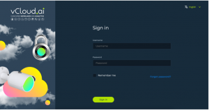
Please enter your valid login and password and click Sign in. After installation you can use the default credentials: admin/admin.
License activation
Go to Settings->Services->VMS->vCloud.ai VMS->VMS License Request, fill the customer e-mail and name fields, specify the required licenses and click Send License Request. Your request will be delivered to vCloud.ai sales team so, in return, you should receive the License activation key file to your email.
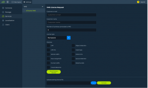
Once received, you can Upload the license file at the screen bottom and click Activate.

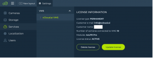
Your license activation page should look as on the picture below:
Adding cameras
Watch How to add cameras video in Cluebase VMS Tutorials on YouTube
8.1. Camera search tool
Camera search tool is created to simplify and speed up cameras discovery and connection processes.
Go to Settings->Cameras->Search
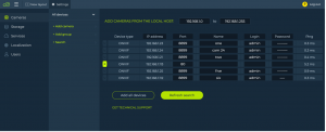
All supported cameras in the local network will be found automatically (normally within 5-10 seconds).
After specifying cameras’ credentials (name/login/password) you can add them one by one using the ‘+’ button on the left

Or you can click Add all devices to add all cameras with the specified credentials.
Click Refresh search to search the network again.
You can specify the search range manually.
![]()
By default the system will search in the current subnet.
8.2. Add cameras manually
Go to Settings->Cameras->Add camera
Name the camera, select connection type (ONVIF or RTSP) fill the IP address and port for ONVIF or the URL for the RTSP, fill Login and Password with camera’s credentials, select the time zone then click Add.
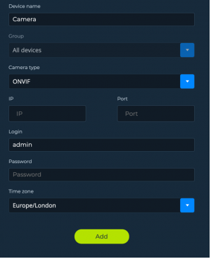
Your camera should then appear in All cameras/Devices section
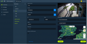
8.3 Create a New Layout for the cameras
Watch Creating a New Layout video in Cluebase VMS Tutorials on YouTube
Storage settings
By default the VMS should identify all mounted drives from the system.
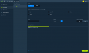
To enable a storage volume for recording please select the storage volume and switch it on:

Then select the cameras that are required to be recorded, set archive depth, select quality and click Save. The storage will be activated for recording immediately.
User access management
10.1. Managing roles
Go to Settings->Users->Add role
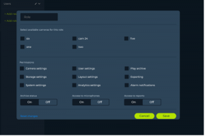
Name the role and grant access to specific cameras and functions. Click save.
Please note that all users with this role will then have access to the specified cameras and functions.
10.2. Managing users
Go to Settings->Users->Add new user
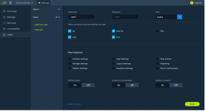
Specify the new user credentials: Username, Password and the required Role. Access granted to the selected Role is be indicated below but is not available for editing. To edit the permissions you need to edit the Role by clicking the pencil button

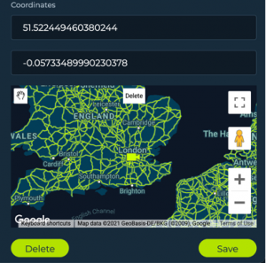
Map setup
To be able to locate the camera on the map you can add the coordinates or simply drag the camera across the map and then click Save.
Layout setup
Click New layout in the main menu
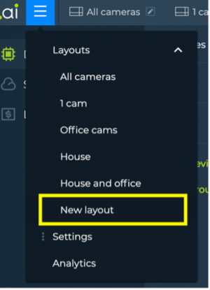
The Layout editing page will open
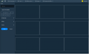
Give your new layout a Name, choose Layout template and drag’n’drop cameras or whole groups to the layout grid on the right-hand side.
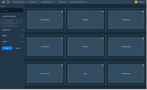
Click Save to save your layout.
To edit existing layouts, click the Pencil button in the layout tab menu at the top of the screen:

Camera groups
Go to Settings->Cameras->Add group and fill the group name field. Then click “Add”
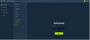
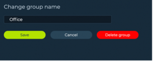
To edit a group click the ‘pencil’ icon on the right side of the group.
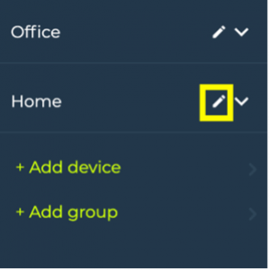
Now you can edit or delete the group.
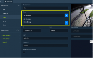
To add a camera to a particular group go to camera settings and select the required group.
Technical support
vCloud.ai technical support is operating 24/7, the average reply time is 3 hours. Technical support can be requested via email: support@vcloud.ai
Cluebase VMS Installation Manual
Preparation
Download cluebase.zip from https://vcloud.ai/downloads and unzip the file. Please note that in some versions of Linux the unzip application is not included so you’ll need to install it separately with the following command:
sudo apt install unzip
Now unzip the Cluebase VMS installer with the following command:
sudo unzip cluebase.zip
The above command creates a directory containing the installation files.
Go to CluebaseVMS directory:
cd CluebaseVMS
Now you have to provide permissions to the installation script (install.sh):
sudo chmod +x install.sh
You are all set for the installation.
Automatic installation
Docker container framework and Docker-compose extension are required for Cluebase VMS installation and operation.
Installing on Linux
Please run the install.sh script to automatically install Cluebase VMS on a clean Linux OS.
To run the script, please go to the folder containing “install.sh” and run the following command:
$ sudo sh install.sh
Installing the SSL version
Here are the steps to install Cluebase VMS with SSL encryption:
- Download Cluebase VMS SSL installer . Please note that it comes as a separate install package and available at https://vcloud.ai/downloads
- Prepare SSL certificate and public key that are generated for the required domain name.
- Unzip the installation package.
- Navigate to ‘certs’ directory in the installation package.
- Copy the SSL certificate and public key (file should be named as follows: cert.crt – SSL certificate, cert.key – public). The existing files should be replaced or removed before
- Provide permissions to the installation script by this command:
sudo chmod +x install.sh
7. Run the installation script:
$ sudo sh install.sh
Manual installation
Installing Docker on Linux
Official Docker installation guide: https://docs.docker.com/engine/install/ubuntu/
Run the following command:
$ sudo apt-get update && apt-get install docker-ce docker-ce-cli containerd.io
Installing docker-compose on Linux
Run the following command:
$ sudo curl -L “https://github.com/docker/compose/releases/download/1.29.2/docker-compose-$(uname -s)-$(uname -m)” -o /usr/local/bin/docker-compose
Grant the necessary access rights by running the following command:
$ sudo chmod +x /usr/local/bin/docker-compose
Preparation for manual VMS installation
You will need to edit the environment variable file, the .env file, to successfully install the VMS.
Please note that this file is hidden in the folder by default.
Open the .env file and specify the server’s IP address in the following fields:
APP_HOST=0.0.0.0 (the server’s public IP address) MACHINE_HOST=0.0.0.0 (local IP address of the server)
If the VMS should only be used in the local network, both IP addresses will be the same.
Using a custom port for the VMS
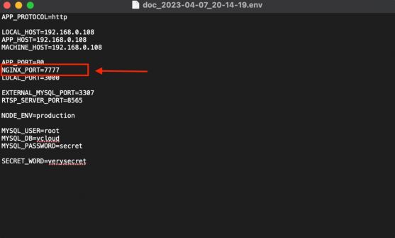
By default the VMS installs and runs on port 80. However you can configure a different port by amending the .env file.
Open the .env file and add NGINX_PORT variable and it’s value (port number) as shown on the screenshot.
Installing and running VMS
Enter the VMS folder and run the following command:
$ sudo docker-compose up -d
This command will automatically download, install and run VMS.
Failover
Description
Cluebase VMS supports failover (hot swap) functionality as the following options:
- 1 to 1 – every server in the system has a failover server
- Many to 1 – several servers can be hot-swapped by 1 failover server
- Many to Many – several servers can be hot-swapped by several failover servers
Important
- In case of using the failover functionality it’s important to make sure that network storage is being used (Object storage or NAS)
- Failover server hardware should be able to handle the required number of cameras so the failover servers’ hardware should be precisely calculated and configured.
- Configuration is automatically sent from main server to failover every 5 minutes
- Please note that shutting down the main server manually is considered as maintenance and will not initiate the failover process.
- After switching back from failover server to the main server it is required to reset failover server’s configuration or reboot.
Setup
To set up a failover system you need to have at least 1 main server and 1 failover server.
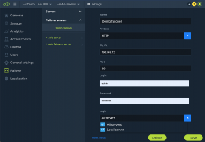
Go to the main server user interface and open Failover settings: Settings->Failover->Add Failover Server and fill the fields with Failover server credentials. In the Logic field choose the server or servers that should be hot-swapped by the current Failover server. Then click Save.
Sign in
Open a web browser (Google Chrome, Mozilla Firefox and Safari are recommended), enter the server’s IP address and press Enter.
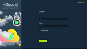
By default login and password: admin/admin.
Stopping the VMS
Run the following command from the VMS folder to stop the VMS server:
$ sudo docker-compose down
Updating VMS
To update the VMS version:
1.stop the VMS
2.Run the following command from the VMS folder:
$ sudo docker-compose pull
3.Restart VMS:
$ sudo docker-compose up -d
Cluebase VMS Architectural and Engineering Specification
General Description
1. Cluebase video management system (VMS) is an enterprise-level client/server-based smart IP video security solution that provides management of video, audio and other data across an IP network. The video management system is designed to work with various ONVIF compliant 3rd party products. Video from other sites may be viewed from single or numerous workstations simultaneously at any time.
2. The video management system can be deployed on a single PC for small or medium system applications or on separate interconnected PCs and servers to meet large systems requirements.
3. The server part of VMS compatible with Linux and Windows OS (64-bit). Though recommended OS for server part is Ubuntu 18.04, 20.04 versions.
4. The server part compatible with ARM, Intel and AMD CPUs.
5. The server part fully docker container-based.
6. The client part compatible with Linux, Windows and MacOS operating systems.
7. There is web-based client. Supported browsers are Chrome, Edge, Firefox, Safari.
8. Client part also has desktop Windows, Linux and MacOS applications.
9. The VMS support cameras compliant to ONVIF Profile S. It is possible to scan the network for ONVIF cameras.
10. It is possible to provide basic configuration of ONVIF cameras from within the VMS, such as general camera settings, recording profiles, audio profiles.
11. It is possible to access camera’s web interface from the link in the VMS.
12. It is possible to use the events provided by an ONVIF camera to trigger events and alarms in the Video Management System.
13. It is possible for operator to control PTZ camera using virtual joystick.
14. It is possible to record ONVIF compliant cameras.
15. It is possible to display ONVIF compliant cameras in live view on a monitor connected to a PC.
16. It is possible to connect cameras or other video sources via RTSP stream to VMS.
17. It is possible to live view and record cameras connected via RTSP.
18. The VMS is designed to use a facility’s existing IT infrastructure.
19. The VMS is capable to be deployed in Local Area Networks (LAN) as well as in Wide Area Networks (WAN).
20. The VMS allows an operator to control and view live and playback streams of cameras and receive alarms from a remote site (across WAN).
21. The VMS is capable to be deployed in the cloud environment (containers, VMs).
22. The VMS allows to view transcoded video streams (live and playback).
23. Live video and archive is played via HLS (HTTP Live Streaming) protocol.
24. The VMS shall allow the establishment of user groups that have access rights to specific cameras, layouts, camera settings, storage settings, system settings.
25. The VMS supports export of the video and frame in the avi, mp4 and jpeg formats to a local or network drive.
26. The VMS is designed in such a way that configuration changes to any part of the system will not interrupt operational tasks.
27. The video management system supports enabling an encrypted communication between the server and client workstation.
28. The server part provides management, monitoring, and control of the entire system. The server part maintains stream management, alarm management, central configuration and user management.
29. The client part provides the user interface for system monitoring and operation. The client workstation maintains live monitoring, storage retrieval, and alarm handling.
30. The video management system supports display of alarms in a special alarm panel.
31. The video management system provides the capability to allow alarms to be filtered by type of the alarm, camera and time.
32. The video management system allows to send an e-mail message in response to an alarm.
33. The video management system allows to send messages to Telegram in response to an alarm.
34. The video management system allows to send messages in the alarm panel, to an email address and Telegram in case of camera disconnection.
35. The video management system supports API that allows for fetching live video streams and archive from 3rd party applications.
36. The video management system provides the user of the client workstation with an option to select the video stream offered by a camera. For cameras configured to use two or more different streams for live view and for recording, operator shall be able to manually switch between the higher resolution stream and the lower resolution stream for a particular camera.
37. The video management system provides the user of the client workstation with an option to enable an automatic switching between a high and a low-resolution stream. The video management system automatically switches to a low-resolution stream, if the user of the client workstation opens multiple cameras on a monitor. The video management system automatically switches to a high-resolution stream, when the user maximizes a camera on the monitor.
38. The video management system support PTZ control with a dedicated graphical (virtual) joystick control, supporting Pan, Tilt, Zoom and Focus commands. For PTZ cameras, the cursor shall change to indicate the Pan/Tilt direction when hovering over the corresponding image pane. The Pan/Tilt speed shall increase as the cursor moves farther from the center of the virtual joystick. An additional control command near the Pan/Tilt command of the joystick shall be used for zoom-in/zoom-out control.
39. The video management system shall support digital zoom of any image pane. The mouse wheel shall control digital zoom when the mouse cursor is hovering over a selected image pane.
40. The video management system provides an instant playback function. Instant playback supports pause, play forward, play reverse, single step forward, single step reverse, fast-forward.
41. The video management system shall support a timeline that provides a graphical overview of video stored on the disk for particular camera. The timeline shall display a timescale that can be adjusted.
Video analytics
42. The video management system provides an integration with a server-based analytics platform.
43. The video analytic processing able to scale seamlessly by adding servers.
44. The system should allow the use of a pool of video analytic algorithm on any camera. It should be easy to change an algorithm from a camera to another.
45. The video analytic processing should be able to run on top of a server or to be virtualized using virtualization technologies.
46.The system can offer the following video analytic:
– Object Detection – identifies people, cars, busses, trucks, motorcycles and animals in a defined area/zone.
– Face recognition – an algorithm for human identification and verification, based on the facial recognition as well as the age and gender estimation. The algorithm creates a database of all faces captured by video cameras and lets you search the database for similar faces.
– License plate recognition – an algorithm for license plate recognition. Video streams can be processed to search for and recognize license plate numbers in the frame. These license plate numbers are saved to a database and associated with the relevant recorded video. The database is searchable. License plate numbers can be compared to lists in real time, with actions performed (or not performed) depending on whether or not a license plate is found in the list. Aside from license plates, system can recognize the make, model, and color of vehicle, as well as the country and direction of movement of the car.
– Traffic Analytics – intended for the calculation of intensity and determination of traffic structure classify the types of vehicles (car, bus, truck, bicycle, motorbike). It also counts people and provides statistical report with graphs and pies by hours, days, weeks, months.
– Crowd Detection – estimates the number of people within a given area in real time and triggers an alarm when a specified number of people (capacity) or a specified percentage of people (occupancy) is reached.
– Hard Hat Detection – detects people not wearing helmets, records video and sends alarms.
– Heat Map – color visual representation of data analysis of customer activity presented by color visual representation of data (warm and cold zones).
– Age & Gender Detection – determines the gender of customers and their approximate age by detecting and analyzing the faces of visitors.
– Motion Detection – captures any movement in the scene. The following rules can be applied: line crossing, loitering, intrusion, abandoned object, disappearance of an object.
– Smoke & Fire Detection – recognizes smoke and fire in the image.
– Smart Tracking System – search people by attributes (color of clothes, bag, hair, hat, gender, and age).
– Body Movement Detection – identifies a person in different positions: sitting, standing, walking, lying, getting up.
– Wagon Identification – detection and recognition of wagon UIC numbers.
– Smart Parking – management of parking lot, detection of license plates of entering vehicles, recognition of model, direction of movement, and payment status of the car.
47.It is possible to setup several “lists” in the database of the analytics platform. A list contains License plates or faces and related data.
48. The analytics platform detects license plates or faces in the live stream provided by the cameras and shall match them against the license plates and faces stored in data-base of the analytics platform
49. When there is a match, an event should be sent by the system to the video management system. Additional data such as the camera and the time of detection should be included in the event provided to the video management system.
50. When the event provided by the analytics platform triggers an alarm in the video management system, the following content shall appear in the alarm panel of the VMS:
– A cropped extract of the original image.
– The corresponding face or license plate taken from the database of the analytics platform to allow the operator to compare the captured image with the reference image from data-base
– Additional data related to the face or license plate stored in the data-base of the analytics platform (e.g. name of person etc.)
51. All events and meta-data are displayed in the archive on a timeline of corresponding camera of the video management system as an icon. If pointing the mouse arrow at this icon, a frame with the image of an object that triggered an alarm should appear.
52. System should support own AI-based embedded human and vehicle motion detection algorithm.
User interface elements
53. Video frame elements:
– Should be able to switch from live video mode to archive mode. If video camera is being recorded switch button should appear as an activate. If not being recorded it should be in inactive status without possibility to click on it.
– Should have button allowing instantly jump back to archive for a predefined number of seconds.
– Should be a possibility to pause live video upon request and restart it by clicking on play button.
– Should have date and time indicator, that allows to access archive at specified date and time.
– Should have object counter element indicating number of detected objects of specific type.
– Should have sound volume bar allowing to control sound from the camera with built-in microphone.
– Should contain video analytics icon allowing to activate embedded AI-based motion detection analytics.
– While clicking on video analytics “ai” icon, settings should be activated allowing to pre-configure embedded AI-based human and vehicle motion detection analytics.
– In the pre-configurable settings, it should be possible to set the following parameters: enable video analytics button, sensitivity option in percentage, view zone button, send to alarm panel button, detections frequency in seconds, delay between detection in seconds, object type selection option.
– If embedded human and vehicle motion detection analytics enabled the “ai” icon should turn green. When disabled it should be of a white color.
– Stream management icon allowing to choose from lower and higher resolution video stream as well as allowing the system to perform automatic stream selection.
– Google maps activation icon. If activated it partially overlays on the live video frame with the option to fully overlay on it indicating camera positioning on the map.
– It should be possible to reload the video stream by clicking on a dedicated icon.
– In the archive mode it should be possible to increase the video playback speed x2, x4, x8.
– Video or frame can be exported by clicking on dedicated icons. Video can be exported in mp4 or avi formats. Frame can be exported in jpeg format.
– It should be possible to expand and narrow down the archive timeline by scrolling the mouse wheel while pointing on a timeline or by clicking on the plus and minus buttons.
54. Upper menu panel:
– All created layouts should appear in the menu panel. Each of them should have unique name.
– All layouts displayed in the menu panel should be editable right from the panel.
– It should be possible to move layouts by holding the mouse cursor and dragging them left and right.
– I should be possible to hide upper menu panel by clicking on dedicated icon in a such way that it appears whenever user point mouse cursor back at the same area.
– There should be an icon on menu panel that allows to work in tutorial mode. Once activated is should be possible to point by mouse cursor at any user interface element and receive short explanation what is this element created for.
– There should be possibility to access expandable main menu from upper menu panel.
– There should be an alarm indicator that changes the color and creates sound whenever alarm is triggered.
55. Alarm panel:
– There should be a possibility to expand alarm panel by clicking on dedicated icon in the upper panel menu.
– Alarm panel should have an option to filter events by: type of event, cameras and time of the event.
– Each video analytics event should contain the following minimum information: frame (picture of the object), type of the analytics, camera, object type, and time and date of triggering.
– If alarm is triggered by face recognition or license plate recognition analytics event may also contain the name of the person from the list.
– There should be “apply” button to filter events and “reset” button to return to default status.
– The latest triggered event should appear in the top of the list.
– Alarm panel should have chat field so different users of the system could communicate through this chat.
56. Layout settings:
– Layout configuration should be accessible from either by editing existing layouts or by accessing expandable main menu.
– Layout settings should consist of: layout name field, layout templates, camera list, groups of cameras and save and cancel buttons.
– System should have the following layout templates: 1 camera, 4 cameras, 9 cameras, 16 cameras, 25 cameras, 36 cameras, all cameras.
– System should allow to add camera by drag and drop method to one of the chosen layouts using mouse cursor.
– System should allow to drag and drop individual camera or the whole group.
– Once layout created it should be possible to change position of live streaming cameras by drag and drop method without accessing layout settings.
Camera settings
57. Camera settings should consist of the following elements: name of the server, camera groups, individual cameras, manual camera adding option, adding group of cameras option, option to bind two or more servers, automatic camera search option.
58. Individual camera setting should consist of the following elements:
– Unique camera number field.
– Device name field.
– Camera ID.
– Camera group field.
– Recording schedule field.
– Camera type field.
– If camera being added through RTSP then RTSP URL field followed by login and password fields.
– Receive event check box for events from integrated cameras.
– Generate RTSP checkbox to create RTSP link.
– PTZ checkbox for cameras added through ONVIF or native protocols.
– Option to reset settings.
– Frame showing camera live stream.
– Option to set camera location on the google map.
– Coordinates filed allowing to set camera on the google map by entering precise coordinates of the location.
59. Manual camera adding option should consist of the following fields: device name, camera type, IP and port fields if camera being added through ONVIF, RTSP URL if camera being added through RTSP, login and password fields.
60.Adding group of cameras setting should consist of add group field and add button.
61. Bind server setting should consist of the following fields: server name, domain or IP address of the server, port, login and password.
62. It should be possible to bind 2 or more servers in the local network or with public IP.
63. It should be possible to bind 2 or more remotely distributed servers each of which is in their own local network using cloud link feature. It should be possible to manage local storage, access camera’s archive, create layouts and receive alarms from all of those binded local servers by 1 or more remote operators.
64.Automatic camera search setting should consist of the following fields: range of IP addresses field, list of discovered cameras including IP address of the camera, camera name field, login, password and ping information in milliseconds, add all devices and refresh the search buttons.
Storage settings
65. Storage setting should consist of the following elements: server name and hard drive discs.
66. Hard drive disk should have the following settings and fields:
– On and off buttons that activate storage.
– Individual camera storage settings section.
– Checkbox allowing to select individual camera.
– Camera unique umber.
– Camera name.
– Archive depths in days field.
– Recording quality drop down field.
– Recording logics drop down field allowing to select the following options: full time recording, scheduled recording or recording by triggered alarm.
– Storage bulk configuration section.
– General storage limit for the selected hard drive in Gb.
– Pre-recording and post-recording fields in seconds.
– Storage capacity bar indicating used space and free space on a hard drive.
Analytics settings
67. Analytics settings should consist of the following elements: server settings, notifications, alarms via emails.
68.Server settings should consist of the following fields:
– Video analytics server URL or IP address.
– Video analytics server authorization API token.
– Option to store metadata in days.
69. Notifications settings should consist of the following fields:
– Send email upon event occurrence with ability to enable and disable this option with the dedicated buttons.
– Send event to Telegram messenger upon event occurrence including fields for Telegram bot API token and Telegram chat ID with ability to enable and disable this option with the dedicated buttons.
– Send notification when camera connection is lost with checkboxes that allow to select where to send. There should be 3 options available: email, Telegram and alarm panel.
70.Alarm via email settings should be available for events from integrated cameras’ edge analytics and should consist of the following fields:
– Buttons to enable or disable receiving alarms form the camera.
– Fields to enter: email address, password, IMAP host and IMAP port.
License settings
71. License settings should consist of two statuses: before the license has been activated and after activation status.
72. License activation status should consist of the following fields:
– Customer email.
– Customer name.
– Number of required camera licenses.
– Type of license allowing to choose temporary or permanent license.
– Send license request button.
– Buttons allowing to upload activation file and activate licenses.
73. After licenses were activated license setting should contain the following information:
– License type: permanent or temporary.
– Customer email address.
– Customer name.
– Number of activated licenses.
– License status.
Users settings
74.Users settings menu should consist of created users and roles assigned to the users, option to add new user and option to add new role.
75. By default, there should be admin role and admin user created.
76. For admin user fields to change user name and user role should be disabled. User name should always remain as admin and user role should always remain as Admin.
77. Add new user setting should consist of the following elements:
– Username filed.
– Password field.
– Dropdown menu to select a role.
– Checkboxes showing cameras that are allowed to be controlled by the user.
– Checkboxes showing current permissions set for the user: camera settings, storage settings, system settings, user settings, layout settings, analytics settings, camera archive access, exporting and alarm notifications.
– Buttons that are enabled or disabled depending on set permissions for the user: archive status, access to microphones, access to reports.
78. Add new role setting should consist of the following elements:
– Role name filed.
– Checkboxes allowing to select cameras to be controlled by the user by this specific role.
– Checkboxes setting the following permissions for this specific role: camera settings, storage settings, system settings, user settings, layout settings, analytics settings, camera archive access, exporting and alarm notifications.
– Buttons that should enabled or disabled the following permissions for the user: archive status, access to microphones, access to reports.
General settings
79. General settings menu should consist of the following settings: video stream, user interface, recording schedules, system information, cloud link, demo mode.
80. Video stream settings should have possibility to set live stream and archive chunk size in seconds.
81. There should be a possibility to enable and disable pulling both camera streams (lower and higher resolution) at the same time.
82. User interface settings should allow to enable and disable automatic page reload after predefined number of seconds.
83. Recording schedules setting should allow to set day of the week and time to schedule the recording of video in the archive. Possibility to create schedule should be easy and intuitive by double clicking on the schedule indicator and dragging the bar from side to side by holding mouse cursor. It also should include list of created scheduled in the drop-down menu.
84. System information setting should include the following parameters: CPU load, RAM load, UI version and server version.
85. Cloud link setting should allow to create tunnel between the server of the user and client machine of the user that connects to the server. By enabling cloud link system should generate URL that should allow the user without any additional VPN or public IP on a server side to connect to the server using his access credentials from any location. Server and client should have internet access.
86.Demo mode setting should allow to enable four video clips that can be used as virtual cameras.
Localization settings
87. Localization setting should contain list of languages with checkboxes. Once user chooses preferred language user interface language should instantly change to the chosen language.
VMS User Manual
