Tiandy Easy7 Smart Client Express User Manual, This user manual is prepared based on Easy7 video monitoring system. In order to provide brief function instruction of the system and help users to systematically understand operation process, this user manual is prepared for reference.
This user manual is prepared based on Easy7 video monitoring system. In order to provide brief function instruction of the system and help users to systematically understand operation process, this user manual is prepared for reference.
[Note] Product real-time update will not be further notified.
N/A
Tiandy Easy7 Smart Client Express User Manual
Read More :
- 3. Usage Attentions
- Current monthly largest quantity of human face pictures received from single channel is 1 million. The current upper limit of quantity of human face pictures received from all channels is 5 million. If the quantity exceeds the upper limit, result of intelligent retrieval cannot be acquired.
- Standalone version can support 500 point locations at most at present.
- Present screen supporting 3,840*2,160 (4K) resolution at most.
- This platform is not compatible with cameras in sky-eye series cameras at present.
- MAC AIO only supports external microphones.
- As for the equipment added in P2P account number way, audio sampling frequency shall be set to be 8kHz. Other sampling frequency may cause program failure on standalone version, so please use it cautiously.
- As for the same NVR and IPC, video playback and video download exist at the same time. 5 channels at most are supported at present. Otherwise, download failure or equipment overload will be reminder in download process and video playback will fail.
- MAC system authorizes standalone version, such as microphone authority. Restart the standalone version.
- As for MAC version, the real-time preview in full screen cannot quit from full screen by pressing ESC (unless equipment list is closed).
- Firewall of computer may influence some normal functions of standalone version. Please add white list or close firewall.
- Software overview
Easy7 Smart Client Express is an application based on MacOS and Windows operation system, which is specially used for managing, previewing and operating network monitoring equipment, suitable for all series of Tiandy NVR, IPC and other devices. The software can realize grouping management of watch points according to different scenarios and customize the group name. It can carry out real-time video browsing, audio preview, voice intercom and other operations based on the device.
It can control the equipment PTZ, set preset position and call. It can switch video playback between user-defined groups, support front-end and local video playback, control playback through time axis, and download video files to the client-side. The rich video monitoring business functions of the software are really suitable for the application of various video monitoring scenarios.
Easy7 Smart Client Express Win64 V8.5.exe can install and operate individually and support Tiandy full series of hard disk video equipment and network video equipment.
CPU: Intel(R) Core(TM) i5, the 8th generation is recommended
Memory: 8G recommended
System: Support Windows 7 64-bit and Windows10 64-bit system
Take the installation of “Easy7 Smart Client Express Win64 V8.5.exe” in Windows 10 64-bit system as an example, the installation of other versions is the same.
- Find the installation file “Easy7 Smart Client Express Win64 V8.4.exe” in installation disk, as shown in the figure below:
P] Easy? Smart Client Express Win64 V8,5.exe
Figure 3.1.1
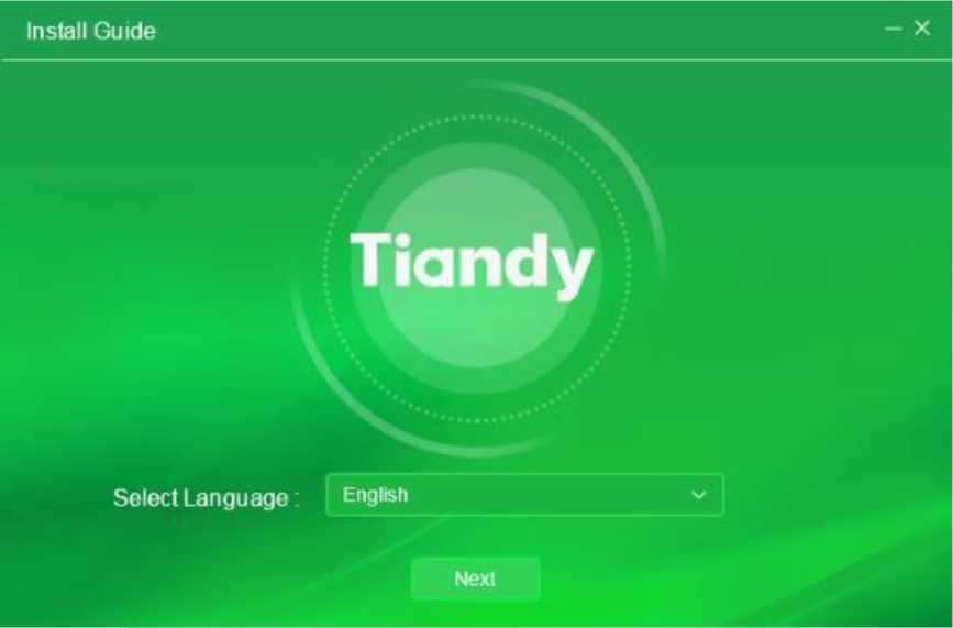
Figure 3.1.2
select “English”, click “Next”. It will be installed on Disk C as shown in the
figure below:
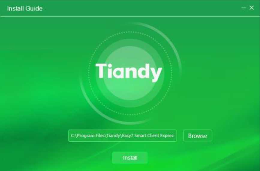
Figure 3.1.3
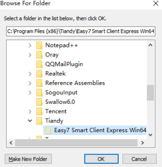
select customized installation directory, as shown in the figure below:
Figure 3.1.4
5) Set installation directory, click “Install” to start installation program,
as shown in the figure below:
Figure 3.1.5

in the figure below:
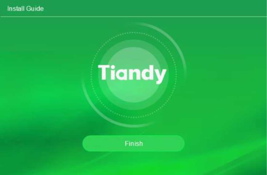
Figure 3.1.6
Temporarily not available.
Take the uninstallation of “Easy7 Smart Client Express Win64 V8.5.exe” in Windows 10 64-bit system as an example, the uninstallation of other versions is the same.
1) Select “Start”->”All program”->”Tiandy”->”Easy7 Smart Client
Express”->”Uninstall”, as shown in below figure:
| V | Tiandy | jjjjj.pny | ||
| O | Easy? Smart Client Express | |||
| ■ | TortoiseSVN | Pin to Start | ||
| V | More | > | ||
| ■ | Video LAN | Uninstall |
Figure 3.2.1
- Click “Uninstall”, enter control panel, select “Program and feature” -> “Uninstall or change program”, then select “Easy7 Smart Client Express”, right key to select “Uninstall” or double click, there will display a pop-up for deletion, as shown in below figure:
 Easy? Smart Client Express Uninstall
Are you sure you want to completely remove Easy? Smart Client Express and all of its components?
Yes
No
Figure 3.2.2
Easy7 related programs and continue uninstallation progress, as shown in the figure below:

Figure 3.2.3
completion, click “Confirm” and the program is completely removed, as shown in the figure below:
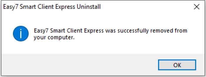
Figure 3.2.4
- Software login and framework setting

Double click the application icon
on the desktop to enter system
login interface, an initial password is required to be set for the first-time log in , as shown in below figure:
Initial password setting X
Tiandy
£ admin
Û Please enter password

Û Please enter the password again
Figure 4.1.1
Note: the password shall be a combination of digits and letters. (Password can be 6-32 characters)
After the initial password is set, enter the password protection setting page, as shown in following figure:
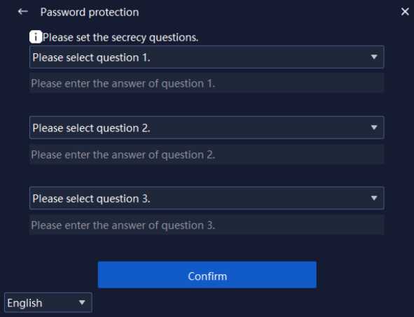
Figure 4.1.2
After the password protection question is set, you will enter the login page, as shown in following figure:
| Tiandy | X | ||
| • a | admin | ||
| Û | Please enter password | ||
| □ Auto 1… □ Save p… Forgot th.. | |||
| Login | |||
| English | ▼ | Server settings | |
Figure 4.1.3
The information of related parameters in log-in interface is as follows:
| Parameter | Description |
| Auto login | Tick and enable the check box. If the user name and |
| password is correct, there’s no need to input user name and password anymore the next time, you may enter automatically.
Cancel automatic login: System configuration -> Common Settings->Login Settings->Automatic Login Software. |
|||
| Save password | Tick and enable the check box. If the user name and password is correct, the current password will be saved and it will automatically fill in the password for the next time. | ||
| Login | Click and enable it. If the user name and password is correct, you may log in the program. | ||
| Forget the password | Click enable and click to enter the password verification page. After the password security question is successfully verified, you can re-enter the initial password setting page to set the password. | ||
| English ▼
English pyccKHÜ Im Ei Tieng viet Le français lingua italiana |
Support shifting between multiple languages. | ||
| x | Click and enable it. Click to close Easy7 login interface. | ||
| Server settings | Stand-alone enabling. Enter database service port No. | ||
| interface through single click. Range of port No.: 1 -65531.
It will take effect after restarting the platform. |
Table 4.1.1
Input correct user name and password, click “Login” to enter the main program interface of Easy7 Smart Client Express. The default grouping is
shown in below figure:
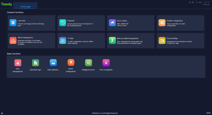
Figure 4.2.1
After entering the interface, click V/’ on the right upper corner of the interface to display version information and date, as shown in below figure:
About
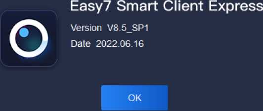
Figure 4.2.2
The mouse slides over “®” on the right upper corner of the interface to display the current CPU occupancy and memory usage, as shown in below figure:
CPU 25.49% | RAM 5381.OOM
Figure 4.2.3
When connecting video, if CPU utilized rate exceeds 75%, it cannot connect to real-time video. As shown in following figure:
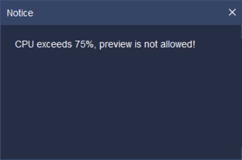
Figure 4.2.4
Click “Ö on the right corner of the interface to lock the interface. When correct delock password (i.e. login password) is input, the screen will be delocked, as shown in below figure:
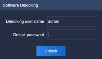
Figure 4.2.5
Only accounts with “system lock-in authority” and “system unlocking authority” are able to carry out delock operation.
Click O’ cancellation button at the right upper angle of interface and a cancellation prompt box will pop out, as shown in the figure below. Click “OK” to exit from the present platform and return to login interface. Click “Cancel” or
x at the right upper angle of prompt box to exit the current prompt box.
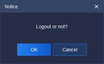
Figure 4.2.6
Click “_” on the right corner of the interface to minimize the program; click “0/0″ on the right corner of interface to restore/maximize the program; click ” x” on the right corner of interface to quit the program.
In order ensure that users may not close the program by mistake in using process, when “x” is clicked to quick the program, a notice will pop up to confirm whether to quit the program, as shown in below figure:
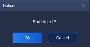
Figure 4.2.7
If “x is clicked by mistake, click “Cancel” to return to previous operation interface; if you are sure to quit the system, click “OK” to quit.
The right upper corner of the interface will display current system time ” to facilitate user to check time at any time.
13:54:38
The navigation menu bar on the top of the interface can be separated from the main interface by dragging the menu, or the position can be exchanged by dragging.
Interface function items are divided into: common functions and basic functions. The module icons in basic and common function area can be dragged separately, and the user can choose the common function for convenience, as shown in below figure:
![]()
![]()
![]()
![]()
![]()

![]()
Tiandy Home page
Common functions
Basic functions
Playback
Search and play the recording file at the nonttonng point
TV Wai
TV wall configuratloo. preview, offline
Device management
Add, modify and delete groups
„ Inlet and outlet management
Jr .’ Face management, human gate real-
Face recognition
, System configuration
Typca operation on client configuration
ElectronicMap
Management and operaton function
eTiandy Co.,Ltd Al Rights Reserved
Figure 4.2.8
Real-time preview: View the live images at the monitoring point.
Video playback: Search and play the recording file at the monitoring point.
Equipment management: General management of monitoring devices to facilitate addition.
System configuration: Typical operation on client configuration.
Alarm management: Real-time indication of unit alarm message to facilitate access to unit exception.
TV Wall: TV Wall configuration, preview, offline switch settings.
Inlet and outlet management: Face management, human gate realtime preview and information query.
ElectronicMap: Management and operation function of electronic map.
Face recognition: Management and distribution of face database.
User management: User password change allowed.
Operation logs: Check the system operations logs to understand the system operation.
Intelligent search: Intelligent analysis information from search, such as face retrieval, indoor electric vehicle testing and so on.
Data statistics: Total amount.
Alarm configuration:Coordinated configuration of various alarms.
[Note] After each login, the module icon will return to the default position, and the navigation menu bar position will be saved as the position when you quit last time.
Click ” ” on the left lower corner of the interface to display real-time
alarm information, as shown in below figure:

Figure 4.2.9
“Real-time alarm” records time, source, type, status, grade and other information of the alarm. When alarm information occurs, click “Play” to check alarm video playback, as shown in below figure:
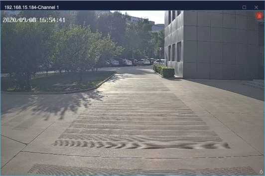
Figure 4.2.10
Click “ ” to enter defense deployment/withdrawal management interface”, where all hosts can be controlled. The defense deployment/withdrawal status of channel and alarm is shown in the figure below:
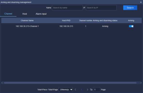
Figure 4.2.11
Click the equipment management icon l j on home page to enter the equipment management interface.
Click “Device” to enter the device management interface. The device interface displays name, device type, IP address, port, video channel, connection status and other basic information of all added device, in which if the connection status is green, it means the device is on-line, and if it is red, it
means the device is offline; addition, modification, deletion and other operation
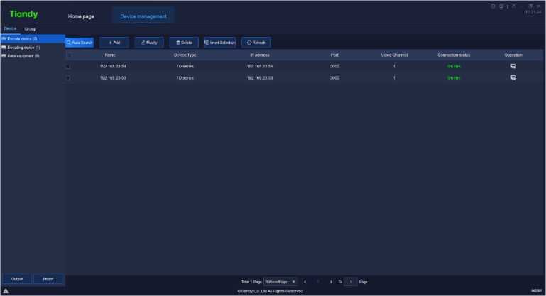
of the device can be conducted. As shown in below figure:
Figure 5.1.1.1
The information of related parameters in the interface is as follows:
Description
Parameter
| Auto Search | Automatically search for devices under the same network segment, batch addition supported. |
| Add | Manually add encode device, support IP method, Standard domain name method, EasyDDNS method , P2P direct connection method, P2P account number method to add device. |
| Modify | Modify information of already added device. |
| Delete | Delete already added device, batch deletion of device supported. |
| Output | Select the device, and output the device information in three forms of Equipment List, Organization Chart, and Organization Relationship Table. |
| Import | Click the device, and input the information in Equipment List, Organization Chart, and Organization Relationship Table, which are contained in the file. |
| Invert Selection | Select all device that are not selected at that moment. |
| Refresh | Update the status of device at current interface. |
| Name | Display the name of all already added device. |
| Device Type | Display the device type of all already added device, TD series (Tiandy series) supported. |
| IP Address | Display the IP address of all already added device. |
| Port | Display the port of all already added device. |
| Video Channel | Display the maximum number of video channels allowed to play of all already added device. |
| Connection Status | Display the current connection status of all already added device. The reason will be displayed, if equipment login fails. |
| Operation | Click and enable it to open the web user-side interface of the device. |
Table 5.1.1.1
Click ”
Q. Auto Search
to enter automatic search interface, as shown in below
![]() figure:
figure:
| Add Device | X | ||||
| 1 | 4-Add | C Refresh | |||
| □ | Device Type | IP address | Port | Channel No. | Product number |
| □ | IPC/PTZ | 192.168.30.28 | 3000 | 1 | |
| □ | IPC/PTZ | 192.168.30.30 | 3000 | 1 | EV-IP-2B20G1-M-28 |
| □ | IPC/PTZ | 192.168.30.32 | 3000 | 1 | |
| [□ | IPC/PTZ | 192.168.30.37 | 3000 | 1 | |
| □ | IPC/PTZ | 192.168.30.41 | 3000 | 1 | |
| □ | IPC/PTZ | 192.168.30.42 | 3000 | 1 | |
| □ | IPC/PTZ | 192.168.30.43 | 3000 | 1 | |
| [□ | IPC/PTZ | 192.168.30.44 | 3000 | 1 | |
| □ | IPC/PTZ | 192.168.30.45 | 3000 | 1 | |
| □ | NVR | 192.168.30.49 | 3000 | 11 | |
Figure 5.1.1.2
Tick and select one or more device in device column, click and a pop-up to add device will display, input the device’s user name and password (it’s recommended to set unified user name and password for severaldevice, if user name or password is wrong, the batch addition of partial device
will fail). If you select to import it into a group, the device will be automatically imported into the group, otherwise you need to manually add to a group, as shown in below figure:
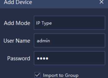
OK Cancel
Figure 5.1.1.3
After addition, it will display the number of device successfully and
unsuccessfully added, as shown in below figure:
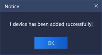
Click ”
O Refresh
Figure 5.1.1.4
to refresh the information of on-line device.
![]()
Click
” to enter device addition interface, as shown in below
figure:
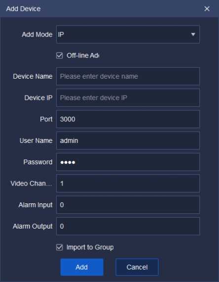
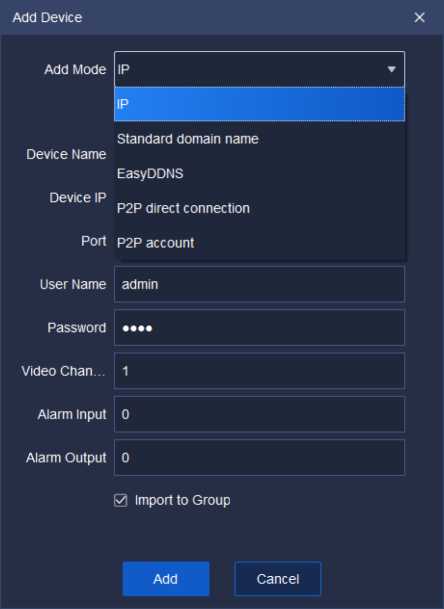
Add Device
Add Mode Standard domain name
Device Name
Device Type
DNS
Port
User Name
Password
Video Chan..
Alarm Input
Alarm Output
Add Cancel
0 Off-line Ad<
| Please enter device name
TD series ▼
I Please enter DNS
3000
admin
••••
1
0
I» 1
0 Import to Group
Add Device X
Add Mode EasyDDNS ▼
Device Name
Device Type
DNS
Port
DNS usern…
DNS passw…
User Name
Password
Video Chan…
Alarm Input
Alarm Output
Add Cancel
0 Off-line Ad<
Please enter device name
TD series
Please enter DNS
3000
Please enter DNS username
Please enter DNS password admin
1
0
I”
0 Import to Group
Add Device X
Add Cancel
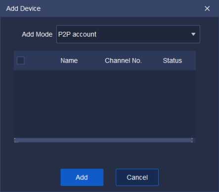
Figure 5.1.1.5
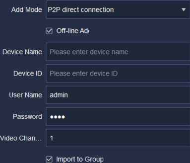
Select device addition type and fill in corresponding device name, device ID, port, user name, password and video channel, and tick to select whether it’s offline device addition and whether needs to import a group according to requirement, the description of related parameter information is as follows:
| Parameter | Description |
| Add Mode | Select different add type: IP type, Standard domain name type, EasyDDNS type , P2P direct connection |
| type, P2P account number.type. | |
| Off-line Add | Tick, then both on-line and offline device can be added. Not to tick, then only on-line device can be added. |
| Device Name | Add device name. ( There’s illegal character limit when adding device name, following characters are not allowed to be input ~!#$%A()=[]{},”:;'<>?*’+/\& ) |
| Device Type | Optional device type: TD series (Tiandy series). |
| Device IP | Add device IP. |
| DNS | Add device DNS. |
| Device ID | This information needs to be typed in when enabling the P2P direct connection adding model.
Find [Device ID] via Device IE->Config.->System Config.->System Maintenance->System Upgrading->Version Info , or Device IE->Config.->Advanced Option->System Settings, then type in the digital characters. |
| DNS User name | It’s necessary to input this information when
EasyDDNS type is selected. |
| DNS Password | It’s necessary to input this information when
EasyDDNS type is selected. |
| Port | Add the communication port of device. |
| User Name | Add the login user name of device. |
| Password | Add the login password of device. |
| Video Channel | Add the total number of video channels the device has. |
| Import to Group | Tick, then the system will automatically add the device to Customized list and create a group (the same as device name). |
| Alarm Input | Number of alarm input ports of the device |
| Alarm Output | Number of alarm output ports of the device |
Table 5.1.1.2
Upon correct information is input, the device will be connected, as shown in below figure:
Notice X
1 device has been added successfully!
OK
Figure 5.1.1.6
Tick and select the device to be modified, click
& Modify
to enter device
information modification interface, as shown in below figure:
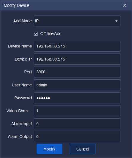
Figure 5.1.1.7
Modification of add type, device name, device type, device IP, port, user name and password, video channel and other related information supported.
Click “Modify” to complete modification, as shown in below figure:
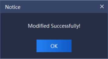
Figure 5.1.1.8
Select one or more devices to be deleted, click
□ Delete
to enter device
deletion interface, as shown in below figure:
Notice
Sure to want to delete the selected host?
OK Cancel
, select
Select one or more devices not to be operated, click
all devices not selected at that moment, and conduct on selected devices.
![]()
Click ”
to refresh the information of all devices on current page.
The operation is the same as 5.1.1 encode device management.
The operation is the same as 5.1.1 encode device management.
Note:
- The device serial number is the factory number of the gate equipment, such asID060218100922201900889.
- When connecting the Tiandy equipment, it should be noted that the port number is 80.
- If the device is configured as Tiandy PAD, you need to enter PAD backend – > communication settings to configure the server address (this address is the IP address of the platform).
Click “Group” to enter group management interface. Information of all devices and customized groups in current system will be displayed, as shown
in below figure:
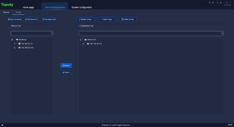
Figure 5.1.2.1
The description of related parameters in this interface is as follows:
Parameter
Description
Set the channel name on the local device tree
0 Sync to device
synchronously to the front-end channel.
Get the front-end channel name of on-line channel in
O Get Device Name
Device list.
O Get alarm port
0 Modify Group
Obtain the alarm input and output information of IPC and NVR equipment.
Select a group in Customized list, click to modify the group name.
+ Add Group
Select the list needs to create sub-group in
Customized list, click to add a group.
Tick and select a Customized list group, click to delete the group and delete the sub-groups and channels in the group at the same time.
□ Delete Group
/I Import
t? Export
Tick and select the channel in left Device list, select a group in right Customized list, click to import the device to the customized device list.
Tick and select the channel in Customized list group, click to export that channel.
Quick search of channel name, input key information
and the channel name including that key information
| will be displayed in Device list and Customized list. | |||
| Sync to device, move the mouse to Device list channel node, click synchronize the channel name to the frontend channel, as shown in below figure: | |||
| □ C ■ My device
□ ffi 192.168.15.191 <?> Channel 1 0 C |
|||
| o | Get the name, move the mouse to Device list channel node, click to get the front-end channel name of single channel, as shown in below figure: | ||
£
( in Device list)
£
(in alarm list )
Modify channel name, move the mouse to Device list
channel node, click to modify the channel name, as
shown in below figure:
El H My device
□ H 192.168.15.191
<?> Channel 1
Upon acquiring the alarming port information of the present equipment list channel, click to modify the name, No. and descriptions of alarming port, as shown
in the figure below:
□ ■ My device
0 <•> 192.168.30.215-Channel 1
âb 192 168.30.215-Alarmln 1 £
192.168.30.215 192.168.30.215-AJan âb 192.168.30.215-AlarmO…
Add group, move the mouse to Customized list group, click to add the sub-group of the group, as shown in below figure:
![]()


| Modify watch point group, move the mouse to | |
| Customized list group, click to modify the name of the | |
| ( in Customized | watch point group, as shown in below figure: |
| list) | 
Delete group, move the mouse to Customized list group, click to delete the group, and delete the sub- |
| groups and channels in the group at the same time, | |
| n | as shown in below figure: |
Table 5.1.2
The information in left Device list is the information of all added encode devices and their channels automatically generated by the system. The right Customized list is the group information customized by users themselves. To facilitate user’s management, users may add the encode device on the left to the Customized list on the right as necessary. For example, to add all channels of device 10.30.10.12 in Device list to the “Group Test” in customized group of Customized list, the operation steps are:
1) Tick and select all channels of 10.30.20.12 in Device list
![]()
10.30.10.12
1) Select the customized group to be added in Customized list
(highlighted when selected)
![]()
![]()

■ Group Test
2)
Click ”
to add channels.
Similarly, select corresponding device channel in Customized list, click ”
t? Export
to delete the device channel from Customized list.
( Note:
Modules other than equipment management all load Customized list, users need to add used devices into Customized list. )
If the name of Channel 1 in device 10.30.10.21 in Device list needs to be modified, click ” —” and a pop-up for modifying device name will display (if the video has been encrypted, it can be decrypted here), as shown in below figure:
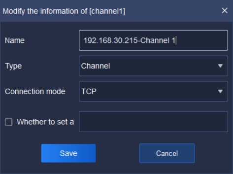
Figure 5.1.2.2
Relevant interface parameters are described as below:
| Parameter | Description |
| Name | Modify the name of present channel. |
| Type | Support the selection of both channel and bayonet. |
| Connection mode | Support three connection modes of TCP, MCAST |
| (RTSP) and MCAST (SRTP). In other words, the platform supports video playing in the form of MCAST (RTSP) and MCAST (SRTP) on the real-time preview interface. | |
| Set password or not | An encrypted video password can be set after enabling. Decrypt video that has been encrypted here. |
Table 5.1.3
If the alarm port 2 in device192.168.30.215 in Device list needs to be modified, click ” —” and a pop-up for modifying device name will display, as shown in below figure:
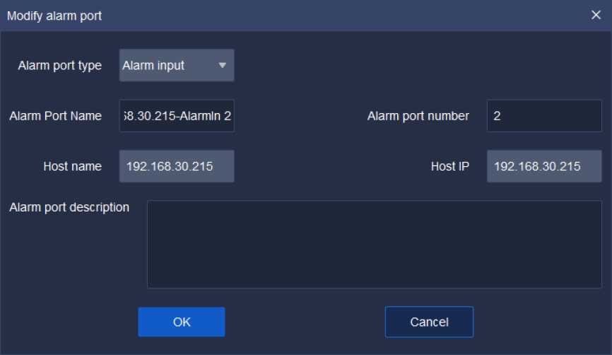
Figure 5.1.2.3
Relevant interface parameters are described as below:
| Type of alarming
port |
Obtain the information about the present alarming port and support two types of ports, i.e., alarm input and alarm output. |
| Name of alarming
port |
Name of alarming port can be self-defined. |
| No. of alarming port | The No. of alarming port can be self-defined (ensure port No. cannot be repeated). |
| Host name | Obtain name of the present host automatically. Modify host name by Equipment-> Coding device -> Modify. |
| Host IP | Obtain the IP of the present host automatically |
| Descriptions of alarming port | Add information about the descriptions of alarming port based as required. |
Parameters
Descriptions
Table 5.1.4
Similarly, select list group in Customized list, click ” —” and a pop-up for modifying watch point name will display, as shown in below figure:
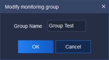
Figure 5.1.2.4

Click the real-time preview icon on the home page to enter real-time
preview interface. The main interface consists of Device list, video preview
window, View, PTZ control ,Senior and Target Information, as shown in below
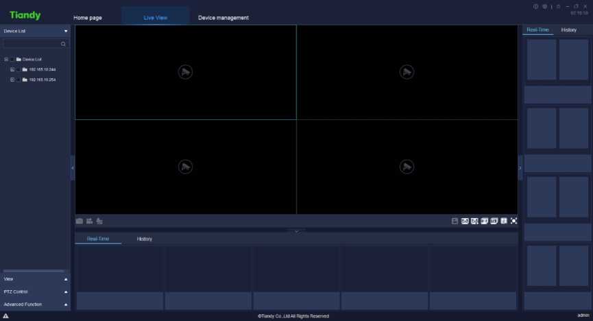
figure:
Figure 5.2
Click “
to unfold or hide the view boxes at the left and right sides.
![]() to unfold or hide the view boxes below.
to unfold or hide the view boxes below.
or
Position the channel node quickly by clicking video window.
The equipment supports video preview and broadcasting by dragging it from group list to window.
Click “Device list” on the left to display all customized group list and input key information in search blank, double click to check device watch point, as
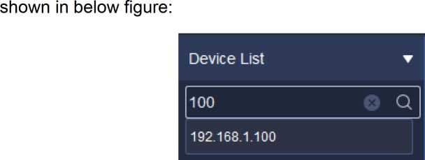
Figure 5.2.1
Click right key on the customized group list and the right key menu of customized group list will pop up, as shown in below figure:
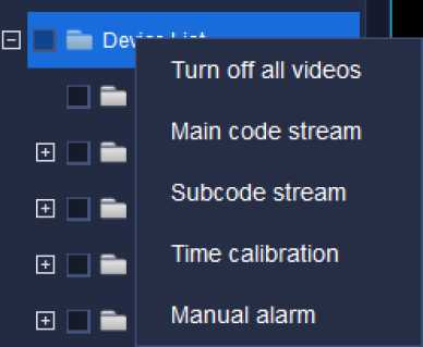
Figure 5.2.1.1
The description of related parameters is as follows:
| Parameter | Description |
| Turn off all videos | Turn off all videos connected at that moment. |
| Main code stream | All the videos in current list are added and played in |
| main code stream mode (as for the channel being played, the playing code stream will not be changed) | |
| Subcode stream | All the videos in current list are added and played in subcode stream mode (as for the channel being played, the playing code stream will not be changed) |
| Time calibration | Conduct time calibration on on-line devices in all group lists. |
| Manual alarm | Cancel the current alarm in the channel in video manually. |
Table 5.2.1.1
Select a group in Device list and click right key, the right key menu of device group list will pop up, as shown in below figure:
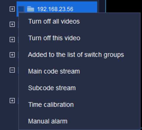
Figure 5.2.1.2
The description of related parameters is as follows:
| Parameter | Description |
| Turn off all videos | Turn off all videos connected at that moment. |
| Turn off this video | Turn off all videos connected in current group. |
| Added to the list of switch groups | Add selected encode device to automatic switch group list. |
| Main code stream | All the videos in current list are added and played in main code stream mode (as for the channel being played, the playing code stream will not be changed) |
| Subcode stream | All the videos in current list are added and played in subcode stream mode (as for the channel being played, the playing code stream will not be changed) |
| Time calibration | Conduct time calibration on on-line devices in selected group lists. |
| Manual alarm | Cancel the current alarm in the channel in video manually. |
Table 5.2.1.2
Select a channel watch point of a device in device list group, click right key, the right menu of device list will pop up, as shown in below figure:
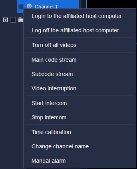
Figure 5.2.1.3
The description of related parameters is as follows:
| Parameter | Description |
| Login to the affiliated host computer | Right click the encode device channel to restore the connection between the device host computer of the channel and Easy7 platform. For example, select Channel 1 in [Device List] in above figure (the affiliated host computer is 192.168.15.191), right click “Login to the affiliated host computer”, the connection status of the host computer 192.168.15.191 is on-line, as shown in below figure: |
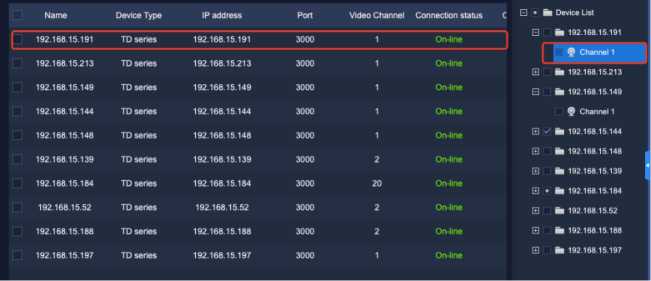
Right click the encode device channel to disconnect the connection between the device host computer of the channel and Easy7 platform. For example, select Channel 1 in [New Group] in above figure (the affiliated host computer is 192.168.15.149), right click “Log off the
affiliated host computer”, the connection status of the host
Log off the
affiliated host
computer
computer 192.168.15.149 is offline, as shown in below
figure:
| Name | Device Type | IP address | Port | Video Channel | Connection status | EJ ■ ■ Device List | ||
| 192.168.15.191 | TD series | 192.168.15.191 | 3000 | 1 | Off line | J | □ ■ 192.168.15.191
n z i |
|
| □ | 192.168.15.213 | TD series | 192.168.15.213 | 3000 | 1 | On-line | Channel 1 | |
| 192.168.15.149 | TD series | 192.168.15.149 | 3000 | 1 | On-line | □ ■ 192.168.15.213
EJ[ ■ 192.168.15.149 |
||
| 192.168.15.144 | TD series | 192.168.15.144 | 3000 | 1 | On-line | E 9 Channel 1 | ||
| 192.168.15.148 | TD series | 192.168.15.148 | 3000 | 1 | On-line | E fc 192.168.15.144 | ||
| □ | 192.168.15.139 | TD series | 192.168.15.139 | 3000 | 2 | On-line | □ ■ 192.168.15.148 g | |
| 192.168.15.184 | TD series | 192.168.15.184 | 3000 | 20 | On-line | □ ■ 192.168.15.139 1 | ||
| 192.168.15.52 | TD series | 192.168.15.52 | 3000 | 2 | On-line |
|
||
| 192.168.15.188 | TD series | 192.168.15.188 | 3000 | 2 | On-line | □ ■ 192.168.15.188 | ||
| □ | 192.168.15.197 | TD series | 192.168.15.197 | 3000 | 1 | On-line | □ ■ 192.168.15.197 |
| Turn off all | Turn off all videos connected at that moment. |
videos
| Main code | In the channel of login encode device, click this button to |
| stream | connect the main code stream video of the channel. |
| Subcode
stream |
In the channel of login encode device, click this button to connect the subcode stream video of the channel. |
| Video interruption | In the channel connected to video, click this button to disconnect the video of the channel. |
| Start intercom | In the channel of login encode device, click this button to talk to the video source of the channel. Click this button in the channel of DVR/NVR device, the intercom box “Talking to XXXX” will pop up to start talking with DVR/NVR; click this button in the channel of IPC device, the intercom box “Talking to XXX” will pop up to start talking with IPC device. |
| Stop intercom | In the channel of login encode device, click this button to stop the intercom with video source of the channel. |
| Time calibration | To conduct time calibration on this on-line device. |
| Change channel name | Change the name of currently selected channel. |
| Manual alarm | Cancel the current alarm in the channel in video manually. |
Table 5.2.1.3
Choose one alarming input port in group in the equipment list, click the right key and the right key menu of equipment list will pop out, as shown in the figure below:
Ş 192.168.30.2′
192.168.““ “
Clear alarm
Figure 5.2.1.4
Relevant parameters are described as below:
| Parameter | Description |
| Manual alarm | If the equipment alarm inputs alarm, click “Manual |
| cancellation | alarm cancellation” to clear the alarm in process. |
Table 5.2.1.4
Choose one alarming output port in group in the equipment list, click the right key and the right key menu of equipment list will pop out, as shown in the figure below:
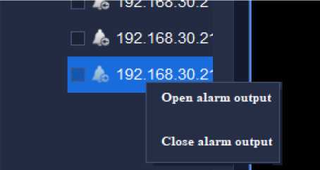
Figure 5.2.1.5
Relevant parameters are described as below:
| Parameter | Description |
| Open/close alarm | Control the on/off status of alarm output port. |
| output |
Table 5.2.1.5
In video preview window, the video will be displayed in the middle, capture menu, video menu and sound menu are in the left lower part, menus can realize its function respectively. Double click video window to maximize it and double click it again to restore, as shown in below figure:
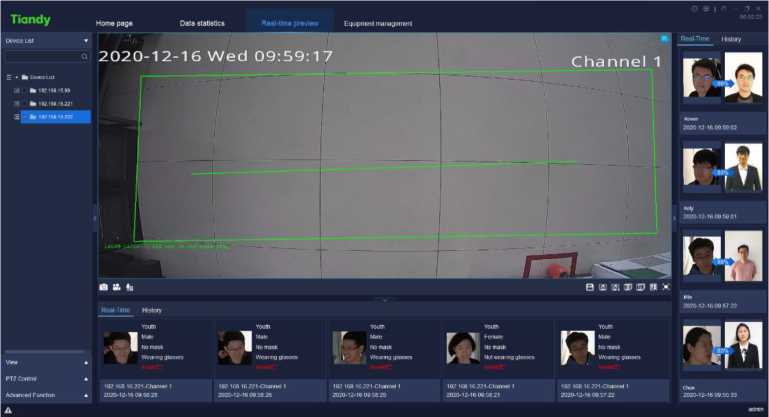
Figure 5.2.2.1
During the video preview, the split screen window will self-adapt to the video according to the number of linked videos, and it supports the real-time video playing of devices added in various ways.
The target bar in the below will display human face information, age, sex, whether or not wearing a mask, whether or not wearing glasses and physical temperature, etc.
The target bar in the right will display the comparison similarity result with the human face database, and the strangers’ face will not be displayed.
When previewing video, the target bar on the right side can display the real-time detected face information.
When previewing video, the status bar at bottom left (in dark color) may display current channel is connecting respectively, audio preview, capture function, instant playback and channel video recording are supported. The channel name will be displayed at bottom right, when the alert is turned on, the right upper corner of the video window will display the alert icon and not to
display it when the alert is turned off, as shown in below figure:
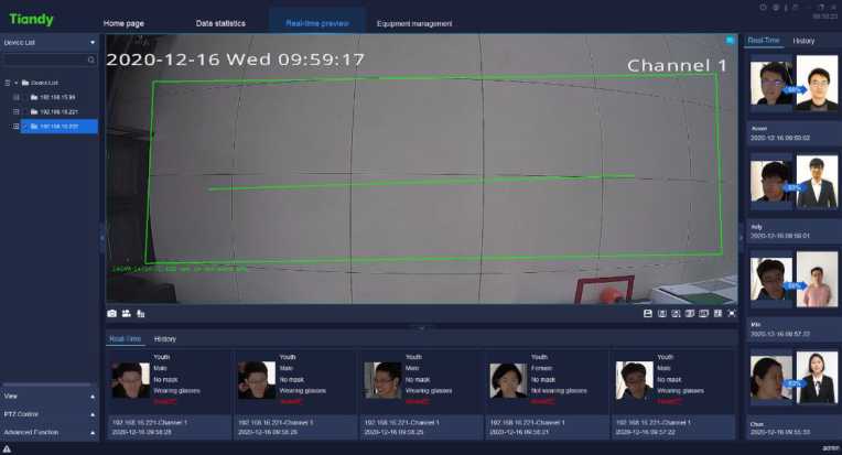
Figure 5.2.2.2
The description of icons in toolbar in video preview interface is as follows:
| Icon | |
| Capture all, to capture windows of all connected |
| videos at current screen. | |
| ilil | Start all recording, record windows of all connected videos at current screen. |
| fc | Intercom list, display current intercom status. |
| Save view, users click to save current view information. | |
| S | Rotating display plan, allow users to set their own switch mode, so that Easy7 can automatically switch video channels on [Real-time preview] interface for users’ convenient browse. |
| El | Start rotating display, automatically switch video channels to preview according to rotating display plan. |
| Group switching list, click this button to display group switching list. There will have devices in the list only when right click the device group in customized device list of device list on the left to select and add devices to [Add to group switching list]. | |
| |jF|j | Last group, which supports the manual switch group to switch the last screen of group. |
| [5~j] | Start/Stop group switching, open video window, click this button to conduct group switching; click again to |
| stop group switching. | |
| Next group, which supports the manual switch group to switch the next screen of group. | |
| o | Set number of video views, click and the setting menu of displayer will pop up. |
| m | Full screen, click to display video window at full screen. Click ESC button or right click the video to cancel full-screen display to escape from full-screen model. |
| Gb | Indicate that the video connecting status is direct connection |
| e | Turn off the video, i.e. disconnect the connection of present video. |
| *»/♦ | Turn on audio / Turn off audio |
| Screen capture, capture the picture of the present videoo | |
| !& | Turn on tape recording / turn off tape recording |
| Instant replay, which supports timely view of present playback based on demands. The time of instant replay can be modified according to System settings -> Video-related -> Time of instant playback. |
Return to preview to exit the page of instant playback.
Table 5.1.2.1
Right click video preview window and the right key menu of video preview window will pop up, as shown in below figure:
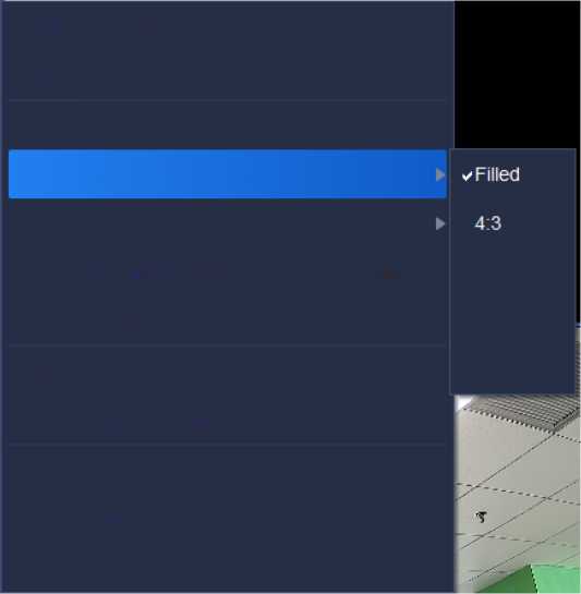
Turn off the video
Audio pre-view
Snap shot
Adjust the video’s aspect ratio
control
Switching of main code and subcode streams
16:9
Video parameter
16:10
9:16
Time calibration
Change channel name
Full screen
Clear alarm
✓ Defence
Figure 5.2.2.3
The description of related parameters is as follows:
| Parameter | Description |
| Turn off the video | Click on the single video window of connected video to turn off the video in the window. |
| Audio pre-view | Click on the single video window of connected video to listen to the audio of video channel in the window. |
| Snap shot | Click on the single video window of connected video to take snap shot of the window. |
| Adjust the video’s aspect ratio | Adjust the video’s aspect ratio, filled, 4:3, 16:9, 16:10 and 9: 16 supported. |
| Control | Electronic amplification and fast ball 3D control are available. |
| Electronic amplification | After enabling the electronic amplification function, press and hold left button of mouse and move the mouse in video & image area to choose the area you want to amplify (roll the pulley of mouse to amplify the image in the area chosen). |
| Fast ball 3D control | By clicking mouse, the scenes monitored are adjusted to video center. In detail:
|
| area chosen will move to the center of the video and amplify.
3. Press and hold the left button and move the mouse upward and leftward to choose a rectangular area. The center of the rectangular area chosen will move to the center of the video and shrinks. |
|||
| Switching of main code and subcode streams | Auto switch between main code and subcode streams. Support simultaneous switch among native video. | ||
| Video parameter | Set the display parameter of currently selected video: brightness, contrast, saturation and Hue. | ||
| Video parameter X
50 * Brightness • 50 □ Contrast * 50 Q Saturation ® 50 • Hue • /♦Restore Default |
Modify video parameters of selected video, restore default supported. | ||
| Time calibration | Conduct time calibration on the on-line device. | ||
| Change channel name | Change the name of currently selected channel. | ||
| Full screen | Display video view window at full screen. | ||
| Manual alarm | Cancel the current alarm in the channel in video manually. | ||
| Defense | Support one-key defense | ||
| deployment/withdrawal function. |
Table 5.2.2.2
The main function of rotating display plan is to allow users to set their own switch mode, so that Easy7 can automatically switch video channels on [Live
View] interface for users’ convenient browse. Notice: A Liveview window supports up to 64 Cameras previews.
After configuring the split screen scheme and the video played, click
” in preview interface toolbar to save view, as shown in below figure:
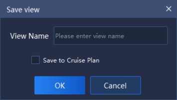
Figure 5.2.2.4
Click view bar on the left and select the view to be added, right click “Add to the regular rotating switch program”, as shown in below figure:
Device List
View
test-face
Name change
Added to the regular rotating switch program
Delete
Figure 5.2.2.5
Click
view rotating display plan interface, as shown in below figure:
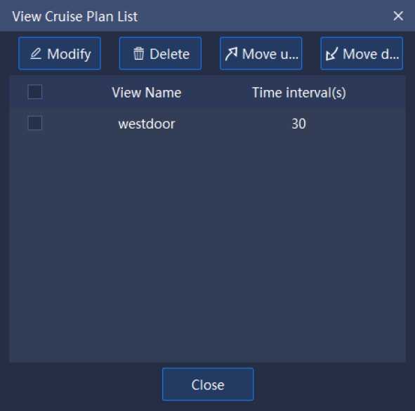
Figure 5.2.2.6
(1) Change the rotating display intervals: tick and select the view to
be modified, click ”
0 Modify
too change the rotating display interval (the
range of interval value is 30~3600s), as shown in below figure:
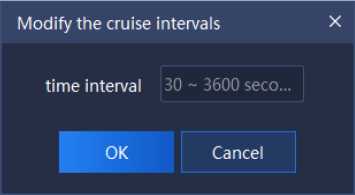
Figure 5.2.2.7
(2) Delete: tick and select the view to be deleted, click
n Delete
to
delete the view, as shown in below figure:
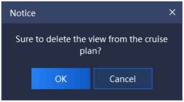
Figure 5.2.2.8
(3) Move upwards/Move down: tick and select the view to be moved,
click ”
/I Move upward
t/ Move down
” to adjust the view play order.
Click ” 3 k” in preview interface toolbar on bottom right to turn on rotating display plan, click again to turn off rotating display plan.
Right click a group in “Device list” on the left, click “Add to group switching list” to add group switching, the pop-up notice box is shown as follows:
Notice X
Succeeded to add to view cruise plan.
OK
Figure 5.2.2.9
![]()
Click
in preview interface toolbar on bottom right to set interval and
group split screen number of group switching, as shown in below figure:
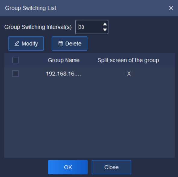
Figure 5.2.2.10
(1) Set group switching interval: set group switching interval in upper part of the interface, the range of interval value is 30~3600s.
(2) Set split screen number, -x- screen (not to change split
screen number and keep original split screen number), 1×1 screen and 2×2 screen supported. Two methods can be adopted
to change split screen number, explained as follows:
©Click ”
0 Modify
to enter Set Split Screen Number
interface;
©Double click the split screen number in Group Split
Screen to set enter Set Split Screen Number interface, as shown in below figure:
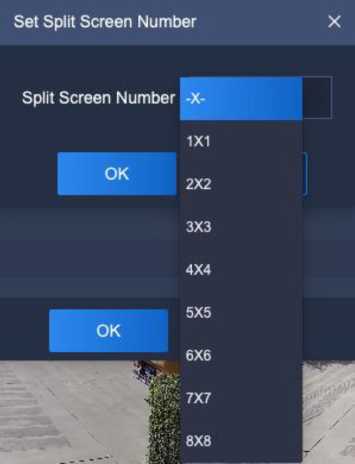
Figure 5.2.2.11
Click “^^” on preview interface toolbar on bottom right to turn on group switching, click again to turn off group switching.
5.2.2. 5. Target Information
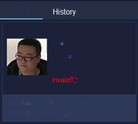
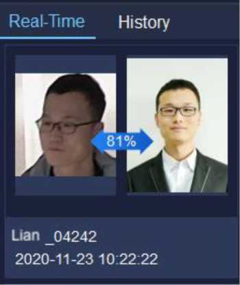
Under and in the right of real-time preview interface, display information of identified persons and the comparison human face database, as is shown in below figure:
Real-Time
Youth
Male
No mask
Wearing glasses
192.16 8.16.22.1-Channel 1
2020-11 -23 10:24:29
Figure5.2.2.12
The target information can identify the person’s age, sex, whether or not wearing a mask, whether or not wearing glasses, detected physical temperature and detection time in real time. At the same time, it can also identify whether the person matches in the human face database. If yes, it can be compared with the pictures uploaded in the database, and the similarity, the name of the person and the detection time will be displayed, otherwise stranger alarm will be on.
If previous record needs to be checked, shift to “History” to check history information.
View list shows currently saved view tag, double click to preview the information of this view. Right click this list view node and a menu will pop up, as shown in below figure:
Name change
Added to the regular rotating switch program
Delete
Figure 5.2.3
The description of related parameters is as follows:
| Parameter | Description |
| Name change | Click to change view name. |
| Add to the regular | Click to add the view to the regular rotating switch plan |
| rotating switch plan | list. |
| Delete | Click to delete this view information node from view list. |
Table 5.2.3
PTZ control may control PTZ speed, preset, etc., as shown in below figure:
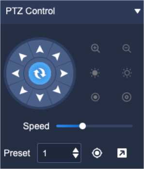
Figure 5.2.4
The description of icons on PTZ control interface is as follows:
Description
Icon
| 8-direction key, press corresponding direction key to control PTZ to rotate in the direction accordingly; the center button is scan shortcut key. | |
| Zoom control button, press “Q” to control the device to perform zoom-out operation, the field of view angle becomes larger and the scene becomes smaller; press “,ja” control device to perform zoom-in operation, the field of view angle becomes smaller and the scene becomes larger. | |
| •*/* | Focus control button, press “^ ” to control the device to perform focusing-in operation, the near scene is clear and the far scene is fuzzy; press ” “ ” to control the device to perform focusing-out operation, the far scene is clear and the near scene is fuzzy. |
| Aperture control button, press ‘©” to control the device to perform aperture reduction operation, press “A:” to control device to perform aperture enlargement operation. | |
| The slider can adjust the rotation speed of the | |
| ■Speed ♦ 1 | |
| device. | |
| Set the preset number for calling. | |
| Call the preset. Select saved preset, click to call and the screen will jump to the preset part. | |
| EJ | Set the preset. Select the preset number to be saved, adjust the screen to the preset to be saved, click Set to save this position. |
Table 5.2.4
Senior may set the light, power and wiper, as shown in below figure:
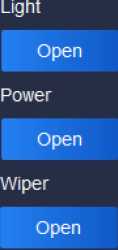
Advanced Function
Figure 5.1.5
The description of related parameters is as follows:
| Parameter | Description | |||
| Light
Open |
Close j | Open/close light. | ||
| 1 | Power
Open |
j Close j | 1 | Open/close power. |
Open wiper.
Table 5.2.5

Click the video playback icon
on home page to enter video playback
interface, query of video recording and time-based video downloading are
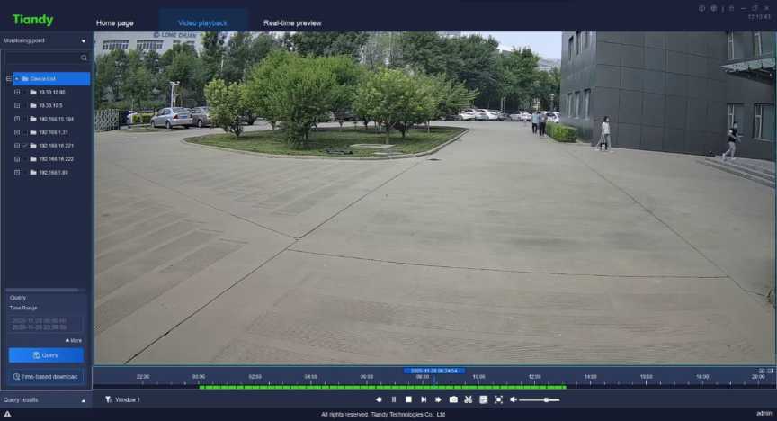
supported, as shown in below figure:
Figure 5.3
In video playback interface, click Watch point on the left, set range of time
for query, if more precise query is required, click
▼ More
to set storage type,
stream type and other screening conditions for query, then click
a More
again
to hide detailed screening condition, as shown in below figure:

Monitoring point
Figure 5.3.1.2
El ■ fa Device List
El !■ fa 10.30.10.80
El \Z fa 10.30.10.5
El I fa 192.168.15.184
El □ fa 192.168.1.31
El 0 fa 192.168.16.221
□ fa 192.168.16.222
El I fa 192.168.1.80
Query
Time Range
2020-11-28 00:00:00
2020-11-28 23:59:59
▼ More
Storage location
Remote storage
Stream type
Mainstream
El Query
(5 Time-based download
Query results j
Figure 5.3.1.1
Select range of time, select the start time on the start calendar of the time range and the end time on the calendar for the end time.
When front-end storage is selected in storage type, following stream types can be selected, both main code stream and subcode stream supported.
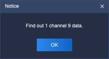
When conditions are selected, click Query to display query result notice box, as shown in below figure:
Click
Query results
below to check current query results, the
expanded interface is shown in below figure:
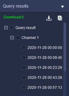
Figure 5.3.1.3
At this time, the query results will be displayed on the progress bar, and users can playback by clicking the time point on the progress bar
Note: The front-end storage video supports synchronous playback (four- channel synchronous playback supports at most).
Play mode 1: for queried videos, double click one video file to realize playback of the file.
Play mode 2: select a playback window, click ► of playback control to realize video playback on time axis related to selected window.
Play mode 3: select a playback window, directly click the time point in time axis to play back from that time point.
5.3.2.I. Playback control
The playback control menu is shown as follows:

Figure 5.3.2.1
The description of icons on playback control interface is as follows:
| Icon | Description |
| On/off synchronous playback; asynchronous playback is set by default. Click to enter synchronous playback mode and click again to exit it. Note: Synchronous playback not supported for local video. | |
| Slow forward button, click to make the video file play slowly.
Note: as for the equipment added by P2P direct connection, click the “slow play” button to slow from 4x to 2x and from 2x to 1x. 1x speed is the slowest. 1/2 speed is not supported. |
|
| Fast forward button, click to make the video file play quickly.
Note: the equipment added by P2P direct connection supports 4X speed playing at most. |
| ► / II | Play/Pause button, click to control the start/pause of video file. |
| N | Step forward button, click to make the video file play frame by frame. |
| Stop button, click to stop the playback of current video file. | |
| Ut*) | Capturing button. Click it to capture the video file that is selected and being played. |
| & | Video clip button: click it to start video clip and click it again to finish that. The time axis of clipped section will become red and the target section will be saved. The format of video saved can be modified by setting “system settings -> video -> download video format”; three formats sdv ,mp4, and avi are available. |
| o | Set screen number button, click to pop up the menu of playback window split screen. |
| 1×1 screen playback supported, click and the video playback window will display in single screen. | |
| 1×2 screen playback supported, click and the video playback window will display in two split screens. | |
| 1×3 screen playback supported, click and the video |
| playback window will display in three split screens. | |||
| 2×2 screen playback supported, click and the video playback window will display in four split screens. | |||
| 3×3 screen playback supported, click and the video playback window will display in nine split screens. | |||
| ■■■■ ■■■■ | 4×4 screen playback supported, click and the video playback window will display in sixteen split screens. | ||
| M | Full screen display button, click to display the playback window in full screen. Click ESC or right click to cancel full screen display to turn off full screen display. | ||
| Volume adjustment bar, drag to adjust the sound of video playback. Click on the horn to turn sound on/off. | |||
| □/□ | Used to adjust the accuracy of time axis. | ||
| Window 1 | Display the current control window number. | ||
| Video type filter button, click to filter the video time axis type, and the time axis of unselected video type will not be displayed. The filter of all types, alarm recording, timing recording and manual recording is supported. | |||
Table 5.3.2.1
In video playback window, right click, and the right key menu of playback window will pop up, as shown in below figure:
Stop playback
Snap shot
Change channel name
Full screen
Electronic zoom
Figure 5.3.2.2
The description of related parameter is as follows:
| Parameter | Description |
| Stop playback | Click to stop the playback of current video. |
| Snap shot | Click to snap shot of selected playback window. |
| Change channel name | Click to change channel name of selected playback window. |
| Full screen | Click to display the playback window at full screen.
Click again to turn off full screen display. |
| Electronic zoom | Click the left button of mouse to choose and zoom in the area. |
Table 5.3.2.2
The downloading is divided into two modes: by file and by time segment.
5.3.3.I. Download by file
In video playback interface, click query result to check query result interface, tick and select several video files and right click, click “^J” to conduct
batch downloading, as shown in below figure:
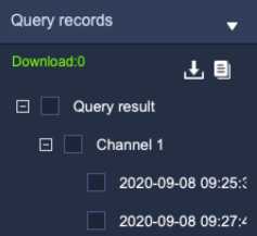
Figure 5.3.3.1
Click ” ” to enter export progress list interface to check the progress of
file downloading, as shown in below figure:
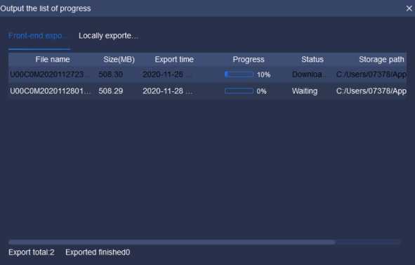
Figure 5.3.3.2
In export progress list, select the file needs to stop export, right click this
file, select
Stop Export
to stop downloading the file, as shown in below figure:
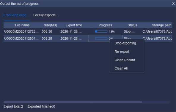
Figure 5.3.3.3
In export progress list, select the file needs to re-export, right click this file,
select ”
ReExport
to export this file again to download.
In export progress list, right click a file, select
Clean Record
to delete all
downloaded records.
In export progress list, right click a file, select
Clean All
to delete all
( Note: When downloading front-end storage video files, only one record file can be downloaded at the same time. )
5.3.3. 2. By time segment
The video on the front-end storage supports downloading by time segment.
Select the channel you want to download (either through the drop-down menu or by clicking the channel in the tree list), select the time segment youwant to download, and then click ”
Q Time-based download
Record the latest video and click to preview it , as shown in below figure:
Recent browsing
192.168.16.221-Channel 1 2020-11-28 00:00:00
Figure 5.3.4
Click the system configuration icon I J on home page to enter system settings interface.
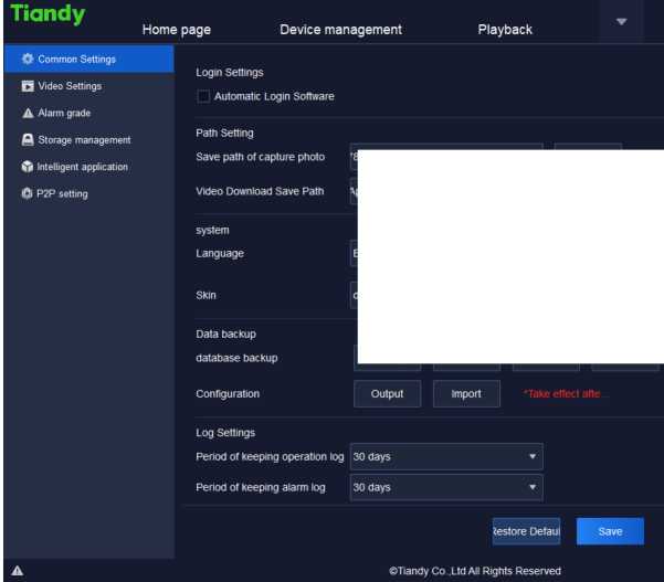
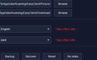 @ © I e (!) – □ x 16:12:10
Figure 5.4.1.1
admin
The description of related parameters in the interface is as follows:
| Parameter | Description | |
| Login
Settings |
Automatic Login
Software |
Tick and select, after fill in correct [User name] and [Password] by users, Easy7 will realize automatic software login function when the operation system starts. |
| Path Setting | Save path of capture photo | The save path of capture, preview and playback photo. |
| Video Download
Save Path |
The save path of video download. | |
| System | Language | Set the language of software system, effective after restart. |
| Skin | Set the skin of software system, effective after restart. | |
| Data backup | Data backup path | Back up, recover, clean up and reindex software database backup
files. |
| Configuration | Import/export relevant configuration information with one key, such as equipment list, user authority and | |
| electronic map. | ||
| Log Settings | Period of keeping operation log | Set the save time of each operation log. |
| Period of keeping
alarm log |
Set the save time of each alarm log. | |
| Restore Default | Restore the configuration of current page to the configuration information when initially installed. | |
Table 5.4.1
| Tiandy | Home page | configuration | ||
| ijt Common Settings | ||||
| Qi Video Settings | ■| □ Automatically restore the stat. | |||
| A Alarm grade | ||||
| Switch between Main and Su… | (•) Automatic O Manual | |||
| ft Storage management | ||||
| 4b Intelligent application | Automatic Switching Screen… | |||
| ▼ | ||||
| i3i P2P setting | Manual Default Connection | Substream | 1 | |
| Play property setting | Good fluency | | * Take effect after replaying video | ||
| Decoding mode setting | Software decode | | ‘Take effect after reboot | ||
| Video download format | SDV format | — | 1 | |
| Preview frame rate | tilde | — | * Take effect after replaying video |
Figure 5.4.2
The description of related parameters in the interface is as follows:
Description
Parameter
| Automatically restore the state last time you exit from the system | The video connected to video preview, when turns on the software again, the video before turn-off will restore connection. |
| Switch between
Main and Sub Streams, Automatic Switching Screen Number |
Set switching screen number, when the number of windows displayed in the client-side video browsing interface is greater than the number of split screens, the connected channel video will default to the subcode stream. |
| Manual Default
Connection |
Set the code stream type of default play. |
| Play property setting | Available to set Good fluency/Minimum delay. Take effect after replaying video. |
| Decoding mode
setting |
Software decode and hardware decoding are supported, effective after restart. Take effect after reboot. |
| Video download
format |
The download recording may set SDV (private format) ,MP4 (general format) and AVI format. |
| Preview frame rate | Show or conceal frame rate on preview screen. Take effect after accessing video again. |
Table 5.4.2
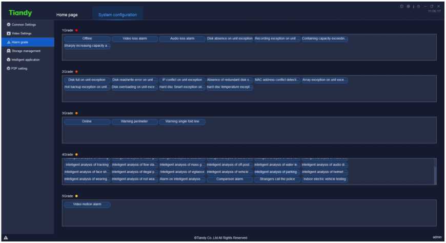
Figure 5.4.3
Drag the alarm type label to other grades to set the type to a new grade.
Alarm grade is used for alarm record filter.
| Tiandy | Home page Device management | System configuration | a û | – □ X 16:14:01 | |||
| Common Settings | |||||||
| Continuous record!… | 30 | ||||||
| Q Video Settings | |||||||
| A Alarm grade | Record format | sdv | |||||
| fl Storage management | |||||||
| Type of recor. .. | Mainstream | 71 | |||||
| Intelligent application | I | ||||||
| ÖI P2P setting | Min. disk space | ® By percentag | … O By space | ||||
| 10 | % | ||||||
| Disk Tull | ® Delete data^ | Stop storing data | |||||
| storage local… | Location | Total size (G) railable space f1; | Available space (G) | ||||
| Store face snapshots and I… | □ C’J | 150 46.5 | 70 | ||||
| DJ | 261 38.5 | 100 | |||||
| □ E7 | 260 7.8 | 20 | |||||
| 260 80.5 | 209 | ||||||
| Restore Default | Save | ||||||
| A | ©Tiandy Co.,Ltd All Rights Reserved | admin | |||||
Figure 5.4.4
The description of related parameters in the interface is as follows:
| Parameter | Description |
| Continuous recording
time (min) |
Set the time of continuous recording (recording packaging), the time range is 5~120 min. |
| Record format | SDV format , mp4 format and AVI format are supported for recording storage. |
| Type of record streaming | Main code stream and minor stream supported. |
| Min. disk space | Supported to set by percentage (%) or by space (G), fill in corresponding parameter in the text box below. |
| Disk full | Supported to select and delete the earliest local recording or stop recording. |
| Storage location | Set the storage location of files. |
Table 5.4.3
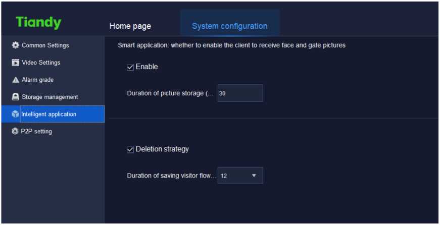
Figure 5.4.5
After ticking “enable intelligent applications”, pictures of human face and man lock can be received. The picture snapshot reserve time can be defined for actual need.
After checking deletion strategy, the strategy can be executed after the upper limit of the stored guest flow duration (6-24 months be supported to choose from) is reached.

Tiandy
Home page
System configuration
Common Settings
Q Video Settings
A Alarm grade
a Storage management
ft Intelligent application
©P2P setting
Figure 5.4.6
| Parameter | Description |
|---|---|
| Region | The place of P2P equipment configuration |
| User name | Enter the user name of P2P mobile phone client side |
| Password | Enter the password of P2P mobile phone client side |
| Log in | Enter correct user name and password to log in successfully. |
| Save | Click “save” to save the current configuration. That |
The description of related parameters in the interface is as follows:
| takes effect after restarting the program. |
Table 5.4.6

Click the alarm management icon
on home page to enter alarm
management interface.
Real-time alarm list displays the alarm received after this login. The list will be refreshed automatically, time of alarm, source of alarm, type of alarm, alarm grade and other alarm information will be displayed, as shown in below figure:
| ® a l a – □
Tiandy Homepage Alarm management Real-time alarm History alarm |
||
| cnee* C)>) Finer level j Select all £ Grade 1 • 0 Grade 2 • £ Grade 3*0 Grade 4 • Grade 5 • | ||
| Time of alarm Source of alarm Alarm Type Alarm status Preview Alarm grade | ||
| A | 2021-11-2511:17:35 192.168.23.53-Channei 1 Video motion alarm Alarm Play 5Grade •
2021-11-25 11:17:33 192 168 23 53-cnannet 1 Video motion alarm Alarm removal 5Grade • 2021-11-2511:17:22 192 168 23 53-Channei 1 Video motion alarm Alarm Play 5Grade • 2021-11-2511:17:04 192.168.23.53-Channet 1 Video motion alarm Alarm removal 5Grade • 2021-11-2511:16:36 192.168.23.53-criannet 1 Video motion alarm Alarm Play SGrade • 2021-11-25 11:16:33 192 168 23 53-cnanriet 1 Video motion alarm Alarm removal 5Grade ■ 2021-11-2511:16:13 192 168 23 53-Ctiannet 1 Video motion alarm Alarm Play 5Graae • 2021-11-2511:16:11 192.168.23.53-Channei 1 Video motion alarm Alarm removal 5Grade • 2021-11-2511:16:00 192168 23 53-cnannei 1 video motion alarm Alarm Play 5Grade • 2021-11-2511:15:29 192168.23 53-Channei 1 Video motion alarm Alarm removal 5Grade • 2021-11-2511:15:19 192168 23 53 Channel 1 Video motion alarm Alarm Play 5Grade • 2021-11-2511:15:09 192168 23 53-Channet 1 Video motion alarm Alarm removal SGrade • 2021-11-2511:12:52 192.168-23.53-Ctiannet 1 Video motion alarm Alarm Play 5Graae • 2021-11-2511:12:47 192168 23 53-Channet 1 Video motion alarm Alarm removal 5Grade ■ HI 0-33 1Ü5 1Î ‘1 (“hanrö 1 Vvtan mntirm alarm Ham mrwu ■ CTianoy Co .Ud Ail Rights Reserved 3 |
|
Figure 5.5.1
The description of related parameters in the interface is as follow:
| Parameter | Description |
| Check | Tick and select alarm records need to be checked, click to fill in handling suggestion, the checked alarm |
| records will be removed from real-time alarm, the handing suggestion and checking status will update to the history alarm record of corresponding alarm record. | |
| Audio | Click to turn on/off alarm audio. |
| Play | Click to play the video 10s before and after the time of alarm, if there’s no video, real-time preview will be displayed. |
| Filter level | Tick and select filter level, the selected level will be displayed in the list, nothing will be displayed if on level selected. |
Table 5.5.1
History alarm list displays all alarms, including checked and unchecked alarms, as shown in below figure:
| Tiandy | Home page | Alarm management | © | 8 | 0 – O X 11:17:56 | |||||||||
| Real-time alarm | i History alarm | ||||||||||||
| Starling time | 2021-11-25 00 00 00 | E | Endtime 2021-11-2523 50 59 E | ||||||||||
| Source ol alarm | Alarm Type | • status check *• | > User check . | «II | ‘ 1 | Query | Reset | ||||||
| Check | Output | Fitter level g | Select all | v Gradel | •/ Grade 2 • -■ Grade 3 | • g Grade 4 • s Grade 5 • | |||||||
| Tame of alarm | Source of alarm | Alarm Type | Alarm status | Preview | Alarm grade | Status check | User check | Time chec | |||||
| 2021-11-25 1117:35 | 192 1662353-Chanoel 1 | Video motion alarm | Alarm | Play | 5Grade | Moi confirmed | |||||||
| 2021-11-2511:17:33 | 192.166.23.53-Ctiarwiel 1 | Video motion alarm | Alarm removal | 5Grade | Not confirmed | ||||||||
| 2021-11-25 11:17:22 | 192.168.23.53-Cnantiel 1 | video motion alarm | Alarm | Play | 5Grade | Hot confirmed | |||||||
| 2021-11-25 11 17:04 | 192 168 23.53-Ctiannel 1 | Video motion alarm | Alarm removal | 5Grade | Not confirmed | ||||||||
| 2021-11-2511 16:36 | 192.168.23.53-criarmei 1 | Video motion alarm | Alarm | Play | 5Crade | Not confirmed | |||||||
| 2021-11-2511:16:33 | 192 1662353-Cnanoel 1 | Video motion alarm | Alarm removal | 5Grade | Not confirmed | ||||||||
| 2021-11-2511:16:13 | 192.166.23.53-CtiarMiel 1 | Video motion alarm | Alarm | Play | &Grade | Not confirmed | |||||||
| 2021-11-25 11 16:11 | 1921682353-cnanoeı i | Video motion alarm | Alarm removal | 5Grade | Not confirmed | ||||||||
| 2021-11-251116:00 | 192 1662353-Ctiarwel 1 | Video motion alarm | Alarm | Play | SGrade | Not confirmed | |||||||
| TotaH 40Piece ToialSPage »ıtemsıpage ▼ < 1 | 2 | 3 | > To 1 | Page | |||||||||
| A | C Tiandy Co .Ltd Ail Rights Reserved | admin | |||||||||||
Figure 5.5.2
The description of related parameters in the interface is as follows:
| Parameter | Description |
| Starting time | Available to set the starting time of history alarm query. |
| End time | Available to set the end time of history alarm query. |
| Source of alarm | Available to set the source of alarm of history alarm query, search by key word supported. |
| Status check | Available to set the checking status of history alarm query, including all, unchecked and checked. |
| User check | Available to set the checking user of history alarm query |
| Query | Click to search history alarm information conforms to search condition. |
| Reset | Click to restore to default query condition. |
| Check | Tick and select alarm records need to be checked, click to fill in handling suggestion. Update verification status, verify users, verify real-time, and process comments after verification. |
| Output | Click to output query results to local device. |
| Filter level | Tick and select filter level, the selected level will be displayed in the list, nothing will be displayed if on |
| level selected. | |
| Play | Click to play the video 10s before and after the time of alarm, if there’s no video, real-time preview will be displayed. |
Table 5.5.2
Click the TV wall icon
on homepage to enter TV wall configuration
interface. There are functions of TV wall configuration, TV wall management
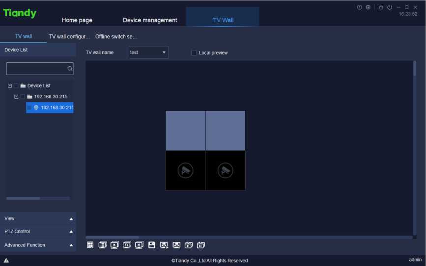
and off-line switch settings as shown below.
Figure 5.6
TV wall interface is mainly used for configuring TV wall video display.
Choose TV wall name on TV wall page to show the current TV wall layout.
Choose a screen that needs video equipment. Choose the video equipment to be added in the left equipment list. One equipment can be added for only one
time.
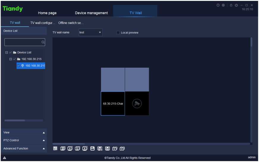
Figure 5.6.1.1
The relevant icons and parameters on the interface are described below:
| Parameter | Description |
| Local preview | After starting preview, videos can be previewed on current TV wall interface. |
| (M) | Set the quantity of screens. 1 screen, 4 screens, 6 |
| screens, 8 screens, 9 screens, 16 screens, 25 screens and 36 screens can be supported for every decoding output channel. Choose decoding output channel and click screen quantity to set the upper limit of screens of the decoding output channel. | |
| | tg]] | Click the button to show switch group list. Click the right button to define the equipment group in equipment list on the left, choose [Add to switch group list] to add equipment in the list. |
| Last group, which supports the manual switch group to switch the last screen of group. | |
| [oil | Start / stop group switch: open video window, click the button to switch group; click it again to stop the group switch. |
| fr]j | Next group, which supports the manual switch group to switch the next screen of group. |
| B | Save the view: click to save the current view information. |
| @1 | View browse plan: users can set suitable switch way and Easy7 can switch video channel automatically on page [Real-time preview], which is convenient for users’ browse. |
| Start view browse and switch video channel automatically for preview according to the view browse plan. | |
| Start all off-line switch, click to enable and start to watch decoding video of all output channels on decoder. | |
| fi fp | Stop all off-line switch, click to enable and start to stop all decoded videos. |
Table 5.6.1.1
If splicing function of equipment is started, click the splicing screen with the right button as shown below.
Picture setting of splicing unit
Create display area
Create all display areas
Close all display areas
All windows zoom to a single screen
Save screen scheme
Application screen scheme
Restart the host
Figure 5.6.1.2
The relevant icons and parameters on the interface are described below:
| Parameter | Description |
| Picture setting of | The quantity of screens set by splicing unit can be |
| spicing unit | defined by user. | |||
| User-defined X
Number of rows Number of columns OK |
||||
| Create display area | Choose the screen in splicing unit, click the right button to create display area. | |||
| Create all display areas | Click the right button to display the screen areas in all splicing units. | |||
| Close all display areas | Click the right button to close the screen areas in all splicing units. | |||
| All windows zoom to a single screen | Click the right button to shrink the maximized screen to the original. | |||
| Save screen
scheme |
Click the right button to save the display plan of screens in current all splicing units. | |||
| Save screen scheme X
Project name Save |
||||
| Application screen
scheme |
Click the right button to apply existing screen plan to current splicing unit. | |||
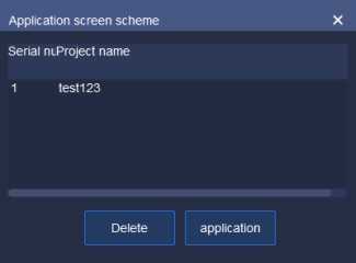
Restart the host Restart the current decoder.
Table 5.6.1.2
The display area created by clicking the right button is shown below.
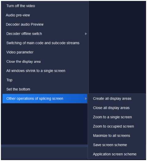
Figure 5.6.1.3
The relevant icons and parameters on the interface are described below:
| Parameter | Description |
| Turn off the video | Close the video preview on current splicing screen. |
| Audio pre-view | Preview the audio effect of current splicing screen. |
| Decoder audio preview | Display audio on decoder. | |||
| Decoder offline
switch |
It is permitted to set video switching of current splicing screen window. | |||
| X
ÇL Offline swtcri setup nitiate offline switch Slop offline «.wile E . Device Lisi Switch para… H Bt 182.1S8.2154 Id . h 102.168.23.55 Stream type Mainstream ‘ Switching fl_ 30 Set Display mode ‘ Move upward Move down Channel Name Length ol stay (seconds) Stream type 192 168 23 541 30 Mainstream 192 168 23 53 1 30 Mainstream |
||||
| Switching of main code and subcode streams | Video preview effect can be switched between main code stream and subcode stream | |||
| Video parameter | The brightness, contrast ratio, saturability and chroma of video can be modified. | |||
| Video parameter X
-A’- _ ” Brightnesi O Contrast Ö Saturatior = Hue /^Restore Default |
||||
| Close the display area | Close current display area of splicing screen | |||
| All windows shrink to a single screen | Shrink all screens to single splicing screens | |||
| Set to top / bottom | Choose the screens in splicing unit, click them to set to top layer / bottom layer. | ||
| Other operations of splicing screens | As for every splicing screen, create / close display area, shrink to the screen, maximize all screens etc.; screen scheme can be saved and applied. | ||
| Create all display areas | Click the right button to display the screen area in all splicing units | ||
| Close all display areas | Click the right button to close the screen area in all splicing units | ||
| Zoom to a single screen | Choose the screens in splicing unit, click to shrink them to a screen. | ||
| Zoom to occupied screen | Choose the screens in splicing unit, click to spread them on the screen fully. | ||
| Maximize to all screens | Choose the screens in splicing unit, click to spread them on all splicing units. | ||
| Save screen
scheme |
Click the right button to save display scheme of screen areas in all current splicing units. | ||
| Save screen scheme X
Project name Save |
|||
| Application screen | Click the right button to apply existing screen scheme | ||
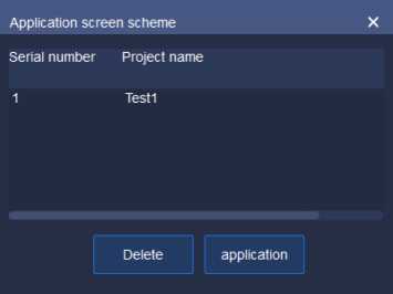
Table 5.6.1.3
5.6.1. 2. Device list
Same as Real-time preview.
Same as Real-time preview.
5.6.1. 4. PTZ Control
Same as Real-time preview.
5.6.1. 5. Advanced Function
Same as Real-time preview.
Wall layout can be configured on the TV wall configuration page. Click the button© to enter the name of TV wall layout and then click “OK”. In this way, the name of TV wall layout can be added as shown below:
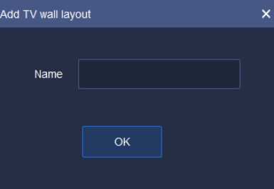
Figure 5.6.2.1
The current name of TV wall layout can be modified by clicking the button
Ö. After clicking “OK”, the name of TV wall layout can be modified as shown below:
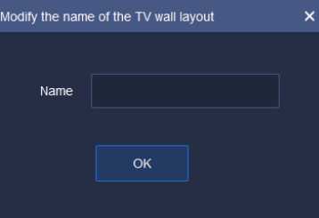
Figure 5.6.2.2
To delete a TV wall layout, choose a layout name and click the button O.
The layout data cannot be recovered after the layout is deleted. Therefore, there is a prompt box for your confirmation. Click “Yes” button to delete the current TV wall layout; click “Cancel” to retain the TV wall layout, as shown below:

Figure 5.6.2.3
After setting the name of TV wall, click the lower configuration list to configure TV wall layout. It supports 1 screen, 4 screens, 9 screens, 16 screens and user-defined screen settings. At the same time, every screen can be adjusted, such as left justifying and right justifying. The parameters and description are shown below:
| Parameter | Description |
| Binding: tick “Decoding output channel” in equipment | |
| list, tick TV wall screen on the right and click it to bind | |
| the current decoding output channel with the screen. | |
| Unbinding: choose TV wall screen on the right and | |
| click it to unbind the current decoding output channel | |
| with the screen. | |
| Add 1 screen | |
| Add 4 screens | |
| Add 9 screens | |
| Add 16 screens | |
| X | Define the rows of screens |
| ■ X | Click to choose the screen to be deleted |
| w | Clear screens: delete all the screens on current TV wall. |
| Left justifying: choose two screens at least and click |
| to justify to the left side of the first screen chosen. | |
| Right justifying: choose two screens at least and click to justify to the right side of the first screen chosen. | |
| Ft | Top justifying: choose two screens at least and click to justify to the top side of the first screen chosen. |
| in | Bottom justifying: choose two screens at least and click to justify to the bottom side of the first screen chosen. |
| :Q | Equalize size: choose two screens at least and click to equalize size with that of the first screen chosen. |
| Ell | Splicing: choose two screens at least and bind decoding output channel. The splicing shapes shall be regular (such as rectangle). Click to splice successfully. |
| El! | Cancel splicing: choose the spliced screens and click to cancel the splicing. |
| Save: Click the button after setting TV wall. In this way, the TV wall screen layout can be saved. |
Table 5.6.2.1
Wall resolution can be configured on TV wall configuration page as shown below. There are three resolutions: 1920×1080 50HZ, 1920×1080 60HZ and 4K 30HZ. If 4K 30HZ is set, decoding can be output from only one route.
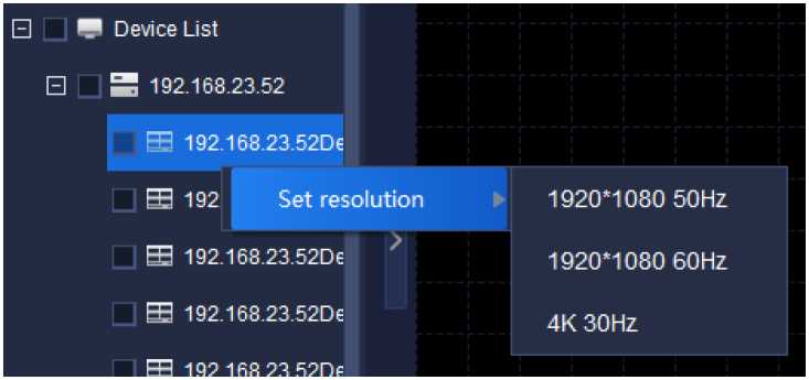
Figure 5.6.2.4
Offline switch configuration is used for TV wall screen switch setting on decoder, as shown below. Code stream type, switch time and display mode of
every decoding output channel can be set.
Tiandy
Home page
Device management
TV Wall
@ © | e (!) – □ x 16:27:49
TV wall
nitiate offline switch
Stop offline switchini
■ Device List
E ■ 192.168.30.215
| Decoding on… | 192.168.30.72Decode output 3 | |||
|---|---|---|---|---|
| Stream type | Mainstream | w | ||
| Switching ti… | 30 | ▲ ▼ | Set | |
| Display mode | Single video | Move upward | Move down |
Decode out…
Channel Name Length of stay (seconds)
Stream type
TV wall configur. Offline switch se…
©Tiandy Co.,Ltd All Rights Reserved
admin
Figure 5.6.3.1
Choose decoding output channel and set display mode (such as sixteenscreens) as shown below.
| Channel Name | 5-nçjtTı of stay (set and’ | Stream type | Channel Name | sngih of stay (second: | Stream type | Channel Name | 2ngth or stay (second: | Stream type | Channel Name | angın or slay (second: | Stream type |
| Channel Name | angth of stay (second: | Stream type | Channel Name | engin of stay (second: | Stream type | Channel Name | angtn of stay (second: | Stream type | Channel Name | sngtn of stay (second: | Stream type |
| Channel Name | ?ngtti of stay (second’ | Stream type | Channel Name | scigth of stay (second: | Stream type | Channel Name | ;ngth or stay (second: | Stream type | Channel Name | ;ngth or slay (second: | Stream type |
| Channel Name | sngth of slay (sec emit | Stream type | Channel Name | jrigiti of stay (second: | Stream type | Channel Name | angth of stay (second! | Stream type | Channel Name | ength of slay (second: | Stream type |
Figure 5.6.3.2
Choose the equipment from the left equipment list for offline switch and
drag the equipment to the channel. In this way, equipment can be added to the
screen. As shown below, click
Initiate offline switcfj
” at top right corner to start offline
switching, or click the right button on screen list to start offline switching. One channel cannot be added to any screen repeatedly.
Channel Name sngth of stay (second: Stream type
192.168.23.53:1
‘ Delete
Delete all
Offline switch
Figure 5.6.3.3
Choose the channels on screen, modify code stream type, switch time and sequence of channels on screen in above decoding output setting.
Relevant parameters on the interface are described below:
| Parameter | Description |
| Initiate offline switch | Click to enable and start it to watch decoding video of the output channel on decoder. |
| Stop offline | Click to enable and start it to stop playing the |
| switching | decoding video. |
| Decoding output
channels |
The equipment supports several decoding output channels. Video effect of every decoding output channel can be set for actual need. |
| Stream type | Set code stream type of channels added to each screen. Choose the channels whose code stream type shall be changed from the following screen list, then choose code stream type from the drop-down box of code stream types. In this way, code stream can be switched.
Note: Before changing code stream type, it is necessary to stop offline switching firstly. |
| Switching time | Set the interval of screen switching (unit: second) in range 10 seconds ~ 1000 seconds. The interval shall be integer. Choose the channel whose switching time needs to change. After changing switching time, click |
| the button “^^^|” to update duration of screen | |
| stay.
Note: Before changing switching time, it is necessary to stop offline switching firstly. |
|
| Display mode | Set the screen display mode of decoding output |
channel, such as single screen, screen in screen,
four screens, 1-5, 1-7, nine screens and sixteen
screens. 1-5 screen means 1 large screen and 5 small screens; 1-7 screen means 1 large screen and 7 small screens. The sequence of channel screens is in accordance with the sequence of addition. To change the sequence, choose channel firstly and
adjust screen sequence by pressing “
Move upward
or
Move down
Note: Before changing channel display
mode, stop offline switching firstly.
Table 5.6.3.1

Click the face recognition icon
, on homepage to enter the interface
of face recognition for face database management, face database download and face configuration as shown below:
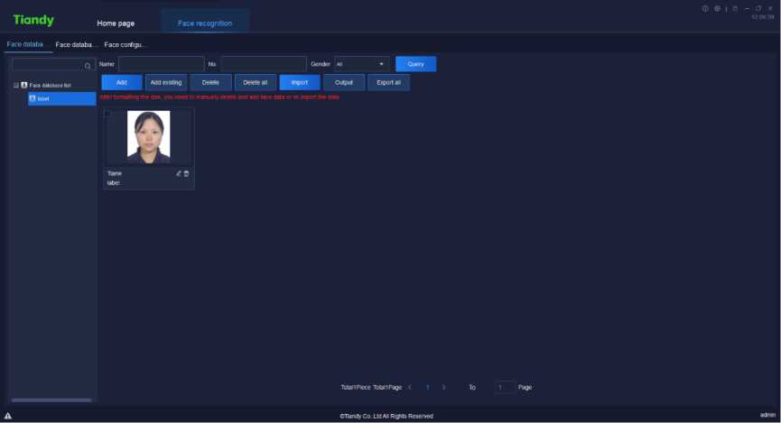
Figure 5.7
Personnel can be inquired based on name, serial number and gender.
Click the right button on left “Face database list”, choose “
Add
”to create
a new face database as shown below:
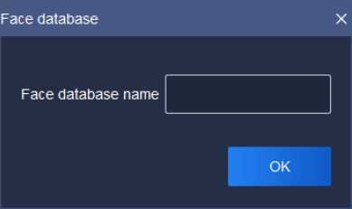
Figure 5.7.1.1
Enter name of face database and click “OK” button to create a new face
database. The name of face database is exclusive.
Click the right button on the name of face database to be modified, choose
enter a new name and click “OK” button to complete the modification.
Modify
Click the right button on the name of face database to be deleted, choose and click “OK” button to delete the face database.
Delete
![]() 5.7.1. 3. Face Image Addition
5.7.1. 3. Face Image Addition
Choose the face database that needs face image addition, click “
to add face image as shown below:
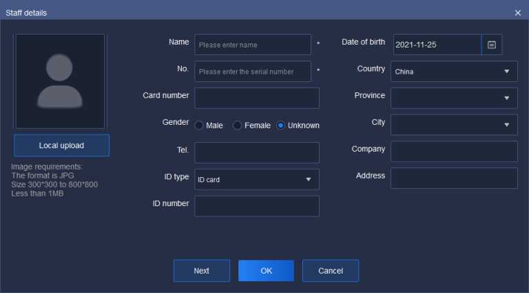
Figure 5.7.1.2
Click “local upload” to upload face image (required item). Image format shall be JPG and the dimensions shall be 300*300~800*800; the size shall not be larger than 1 MB. The image shall be clear enough for easy face recognition.
Enter name of the image (required item).
Enter corresponding serial number of the person (required item). The serial number can be 0~ 999999999.
Other items are not required and can be filled in for actual demand.
![]()
Click “
” to save information of the current person and create a new
page of person information.
![]()
Click “
” to maintain current personnel information and close the
page.
Click “
Cancel
” to close the current page of personnel information.
![]()
Choose a face database, click “
” and choose the personnel to be
added as shown below; click
” to complete the addition. The page
of
current personnel can be closed by clicking
Cancel
Figure 5.7.1.3
![]()
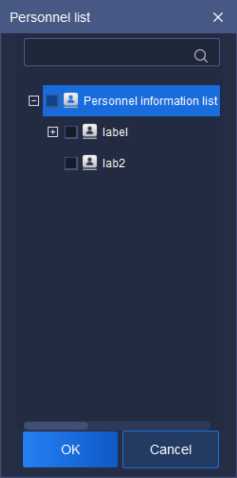
![]()
Choose the face image to be deleted, click “
” to delete the chosen
image; to delete all face images, click “
Delete all
1) Import
Click “ I”
to enter the import page as shown below. Click “download
import template” to download template of personnel information.
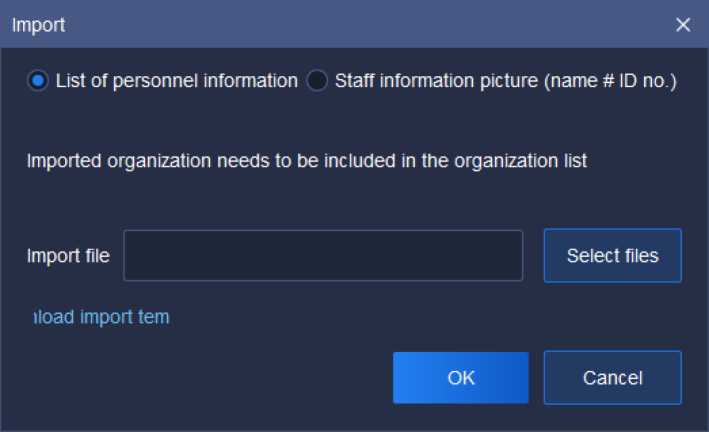
Figure 5.7.1.4
Fill personnel information in the template as shown below:
AttentiorUse the 1
Province City Address Company ID type ID numbeiImage patFace library name
Tianjin Tianjin Xiqing Di**** Co., ID card r12011120CC:/FacePiFace database
Personnel Serial ntCard numtGender (nphone nmrEirthday Country
Zhang Sa/123 r6666 Female ‘12345678^2000-01-lChina
Figure 5.7.1.5
Tick “personnel information sheet” or “personnel information image (name
# job number)”, click “
Select files
” to import file, click “OK” to upload the file; click
cancel” to close the page.
Choose the channel of face database download from left “equipment list”
(the channel shall support face recognition).
Tiandy
Home page
Face recognition
Facedataba… Facedataba… Face configu…
q I Add Remove Copy to
□ ■ Device List Q Face database nchronous stat
E M 192.168.23.54
E M 192168.23.53
Operation
©Tiandy Co.,Ltd All Rights Reserved
admin
Figure 5.7.2.1
![]()
Click “
” to choose a face database to be synchronized, then click
“OK” as shown below.
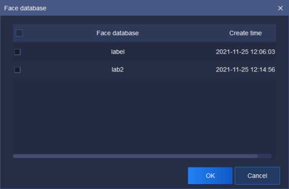
Figure 5.7.2.2
Status and result of synchronization can be seen on current page. If the
synchronization fails, click “operation result” on “operation” page to find information of synchronization failure as shown below. If you want to try
synchronization again, choose the content to be synchronized and click
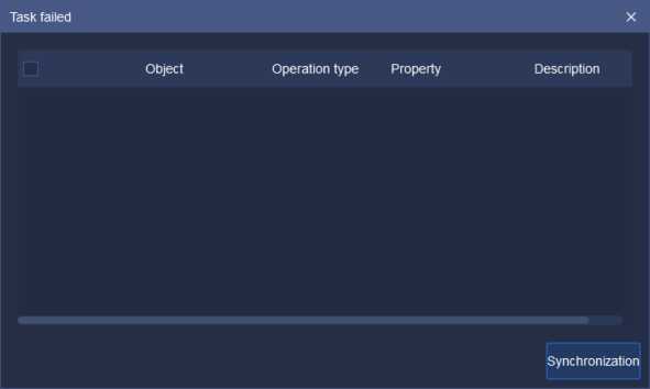
![]()
Click “
Click “
Figure 5.7.2.3
” to delete the current face database in current channel.
Remove
” to copy it to other channel.
On the page of face configuration, face database can be started for current channel; face similarity can be set as shown below.

Device management
| Facedataba… | Facedataba… | Face configu. | ||
|---|---|---|---|---|
| Q | Similarity so | % (1-100) | Set |
Homepage
Face recognition
□ ■ Device List Face database
Enabled
E M 192.168.23.54 label
E M 192168.23.53
E M 192.168.16.221
□ M 192.168.18.103
Ş 192.168.18.103-Chani
©Tiandy Co.,Ltd All Rights Reserved
admin
Figure 5.7.3.1
5.8. Inlet and outlet management
Click the exit I entrance management icon
on homepage to enter
exit I entrance management page. Human gate and vehicle gate can be managed as shown below.
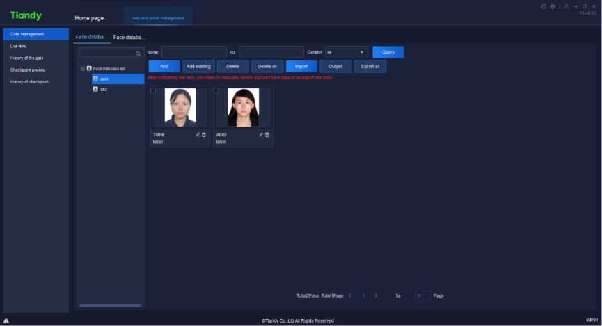
Figure 5.8
Same as face recognition.
Same as face recognition.
Same as face recognition.
The monitored areas can be previewed on the page of preview as shown below. Equipment gate opening and lifting linkage is supported.
X Gate management
A Lw view
A History of the gate
R Checkpoint preview
A History of checkpoint
PAD
Open pate
Oîlamly Co..Lid AH Rights Reserved
Figure 5.8.2.1
Click the right “ ” to unfold equipment list, set real-time equipment preview
sequence and the equipment shown. As shown below, choose the equipment
to be moved, click “
Move upward
or
Move down
” to change the sequence.
| Device
PAD |
> | ||
| <i | ■İlli | ||
| Move upward | Move down |
Figure 5.8.2.2
On the page of human gate history, access areas, user name and access
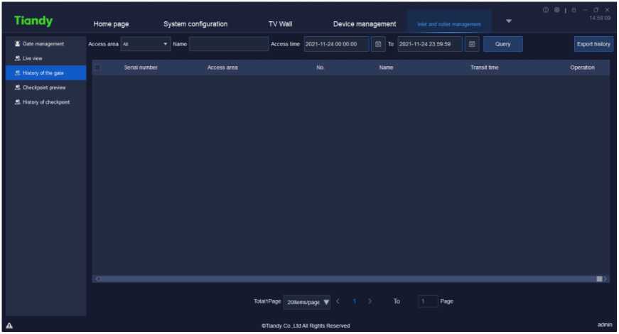
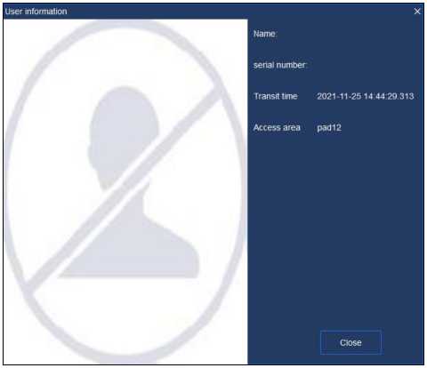
time can be searched as shown below.
Figure 5.8.3.1
Click “
View
” to find access information of the user as shown below.
Figure 5.8.3.2
Real-time captured image at checkpoint in current monitored area can beseen on the page of checkpoint preview as shown below. Information of vehicle
can be found.
Tiandy
Home page
System configuration
TV Wall
Device management
ft Gate management
S. Lnewew
A History of the gate
A Checkpoint preview
A History of checkpoint
License plate number
Vehicle color
Vehicle brand
Channel number
Vehicle type
Transit time
Driving direction
OTiandy Co Ltd A* Rights Reserved
admin
Figure 5.8.4.1
Click the right “ ” to unfold equipment list, set real-time equipment preview
sequence and the equipment shown. As shown below, choose the equipment
to be moved, click
Move upward
or
Move down
” to change the sequence.
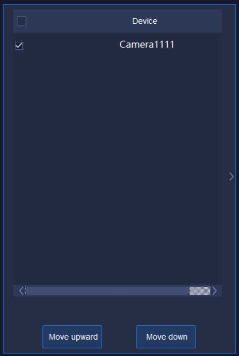
Figure 5.8.4.2
Access area, license plate number and access time can be searched on the page of checkpoint history as shown below.
X Gate management
A Lm view
A History of the gate
Access area aii t Number of license plate
Serial number Access area
Access tme 2021-11 -24 00 00 00 0 TO 2021-11-24 23:59 59 m
Number of license plate
Transit time
Operation
A Checkpoint preview
A History of checkpoint
Totall Page 20ltems/page ▼ < 1 > To
OTtandy Co. .Ltd AH Rights Reserved
Figure 5.8.5.1
Click
View
to find access information of the vehicle as shown below.
Figure 5.8.5.2
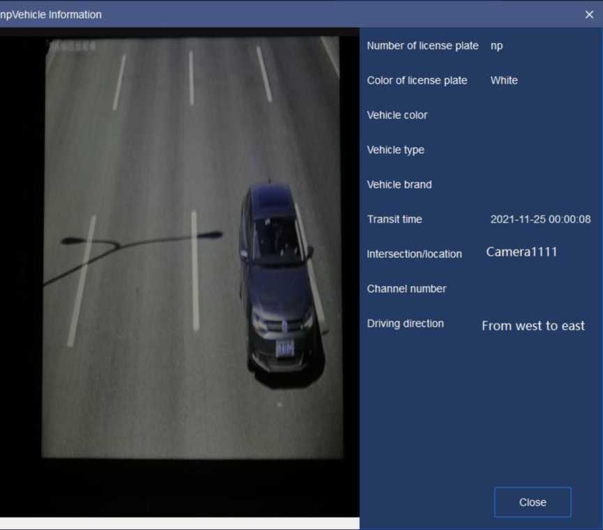

Click the electronic map icon
on homepage to enter the page of
electronic map management and operation as shown below.
Figure 5.9
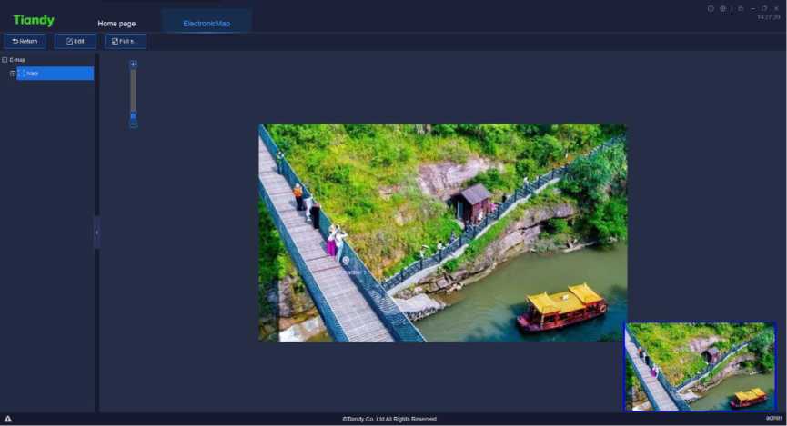
Drag the image manually or operate mouse wheel to change position of the image or zoom it in.
![]()
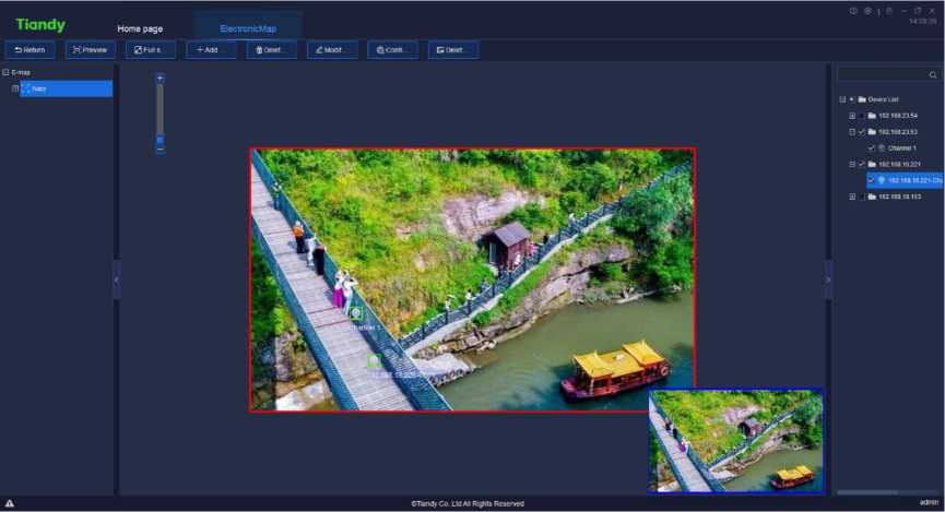
Click
“to configure the electronic map as shown below:
Figure 5.9.1
![]()
Click “
, as shown below, enter map name and choose route of
map, click “OK” to save the current map; or click “cancel” to close the current
page.
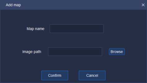
Figure 5.9.1.1
![]()
Choose an electronic map from right list of maps, click “
” and there
will be a prompt dialog box as shown below. Click “Yes” to delete the electronic map; or click “cancel” to close the prompt dialog box and the map will not be
deleted.
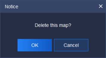
Figure 5.9.1.2
If you want to modify map name or the base map, you can click “ as shown below, click “OK” to save the current map; or click “cancel” to close the current page.
| Modify map | X | ||
| Map name | Nacy | ||
| Image path | J6e35317d777a5bf06cb6c a.jpg | Browse | |
| Confirm | Cancel | ||
Figure 5.9.1.3
In the self-defined equipment list on the right of edit interface, choose the equipment to be added to the electronic map, drag it to the area that needs the equipment. In this way, data collection channel can be added. Drag channel
equipment icon “ ” to change addition position.
Add alarm two nodes, including alarm input
and alarm output
in
electronic map and the input node will lash upon receiving the alarm of alarm input;
cancel alarm
Clear alarm
‘via the right key menu. Alarm output can be used for
controlling two status
Open alarm output
Close the alarm output
” of alarm output on and off via right key
menu.
If the equipment was added, “added already” will be prompted as shown
below.
![]()
Channel 6 Added
![]() To delete equipment, choose the equipment and click the right button on
To delete equipment, choose the equipment and click the right button on
![]() ; or choose the equipment in the left list of electronic maps, click
; or choose the equipment in the left list of electronic maps, click
” to delete the equipment on the current electronic map.
5.9.1. 5. Configure Hot Zone
![]()
![]()
Click
” to link other electronic maps on the current electronic map
as shown below. Tick the left electronic map and click “
” to add the
![]()
” to move back
E-map Related hot zone
Figure 5.9.1.4
electronic map to the right linked area; or click electronic map from right linked area to area of electronic map. Click “OK” to show the hot zone icon “-•” on current electronic map. Drag it to set position of hot zone anew. Or click “cancel” to close the current page.
Configure hot zone X
![]() To delete the hot zone, choose it and click right button on this way, the hot zone can be deleted from current electronic map.
To delete the hot zone, choose it and click right button on this way, the hot zone can be deleted from current electronic map.
. In
![]()
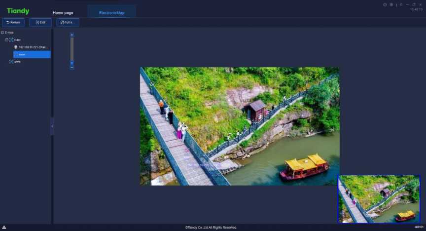
Click “
to preview current electronic map as shown below.
Figure 5.9.2.1
On the page of electronic map preview, the image can be dragged
![]() manually to change its position; or operate mouse wheel to zoom in.
manually to change its position; or operate mouse wheel to zoom in.
Click “
” to preview the image on the whole screen.
![]()
Click “
” to return to the last step.

Click the user management icon on home page to enter user
management interface. The interface will display the basic information of all added users at that moment, as shown in below figure:
All rights reserved Tiandy Technologies Co. Ltd
Tiandy
Home page
Uier management
Real-time preview
adminO!
tKlmiri
Figure 5.10
[ Note ] Only admin-super administrator account has the authority to enable this function.
Click
Add
to enter Add user interface, as shown in below figure:
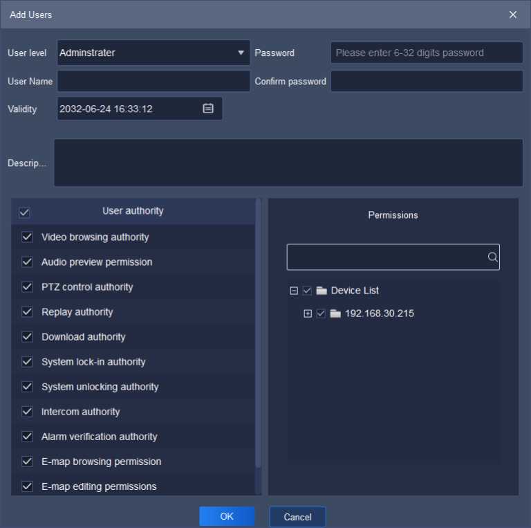
Figure 5.10.1
The description of related parameters in the interface is as follows:
| Parameter | Description |
| User level | Set administrator or operator for current system. |
| User name | Users to fill in any name.
[Note] There’s illegal character limit when adding user name, following characters are not allowed to be input ~!#$%A()=[]{},”:;'<>?*’+/\&. |
| Password | To set password for newly added user. |
| Confirm password | Needs to be the same as input “Password”. |
| Validity | Set the expire date of the authority for users. |
| Description | Supplement and describe user information. |
| User authority | Set the user authority of administrator or operator, such as the authority of video browsing, audio preview authority ,PTZ control, video playback, video download, system lock, system delock, intercom, alarm check, etc. |
| Permissions | Set devices permit user authority to apply. |
Table 5.10.1
Note: Audio preview authority is mainly used for controlling the playing of all audios in the control platform.
( 1 ) Audio preview authority, cloud platform control authority, video playback authority and video downloading authority are based on view preview authority. In other words, if any one of video preview authority, cloud platform control authority, video playback authority and video downloading authority of one channel needs starting, start video preview authority first;
( 2 ) Talkback authority is based on audio authority. Talkback authority of the host can be enabled, when audio authority of at least one channel under such host has been enabled;
to enter Change
Select the user needs to be edited, click
users interface, as shown in below figure:
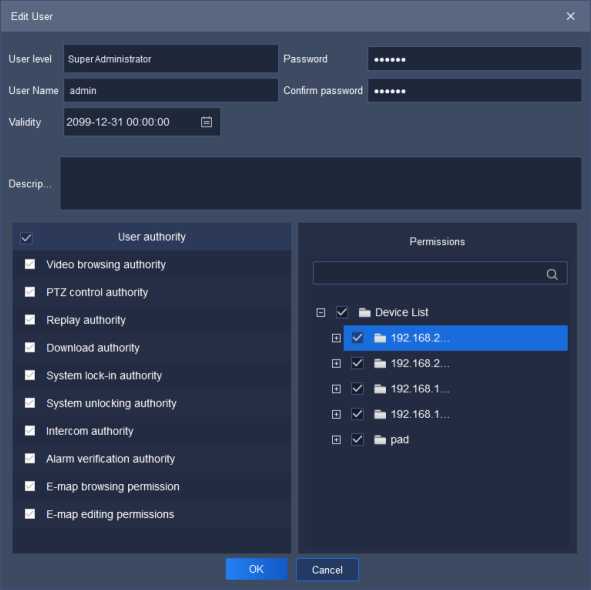
Figure 5.10.2
In the editing interface, the related information of the user can be changed, including user level, user name, validity, password, description, user authority and permissions. Admin-super administrator can only change password.

Select the user needs to be deleted, click
and a notice box
will pop up, as shown in below figure:
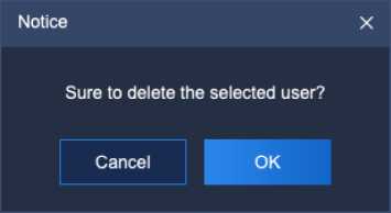
Figure 5.10.3
Click “OK” to delete the selected user; click “Cancel” to cancel deletion.
[Note] Several users can be deleted at the same time.

Click the intelligence retrieval icon
on home page to enter the
intelligence retrieval interface.
| Tiandy | Homs page | Intelligent search |
| • f. J, _ | Device LISI | |
| Startime 2021-11-2300 00 00 S Endtime 2021-11-25 23 59 59 (Ş) Gender «U ‘ Age group *» ‘ | ||
| Wearing mas* m » Wearing glasses « • Body temperature measurement AM » Retrieve | ||
| □ • a Deoust | ||
| y’ 192168 2354 | Output Export all Select al twit Selection | |
| El *1» IM 2353 | ||
| üst Figure | ||
| El k 19216816221 | — | |
| b IM | 2021-11-2515 55 41 ‘charmeM Male Youlh glasses Nomas* Invalid twaas Plartrack | |
| □ k 192 168 23 S4 | ||
| 2021-11-25 15 55 41 ‘^L’88‘8, Male Youth Nomas* invalid Dois Pia>M<*
Channel 1 glasses |
||
| 2021-11-25 15 55 41 1^?’88‘8, Male Youth Homas* invalid OOls PiaıMr» | ||
| Channel 1 glasses
2021-11-25 15 54 05 ”JL’88‘8, Mie Youth Homas* invalid OOls Piaitadr Channel 1 glasses |
||
| 2021-11-2515 54 05 ,^„188 J,8, Male Youth M^,^2″9 Homas* Invalid OOls Piartwr*
Channel 1 glasses |
||
| 2021-112515 54 05 1?„!??, J,8, Male Youth Notwearng Moma5k «valid OOls Pl art»»
Channel 1 glasses |
||
| 2021-1125 15 53 38 ‘onarmeM Ma(e Youth Unknown Nomas* Invalid Mali Piartar* | ||
| 2021-11-2515:53:37 1 CharmeM Male JunKx Unknown No mas* invalid OOls Piartar* | ||
| 2021-11-2515:53:37 ‘^cnarmeM Mae Voultl Unknown Nomas* invalid OOls Piartwr* | ||
| 2021-11-2515 52 46 J,8, Male Youth Unknown Nomas* invalid OOls Piartoa
Channel 1 |
||
| 2021-11-2515:51:10 15?-.16ll8. Male Junior Unknown Nomas* invalid nois piartaa
Channel i |
||
| 2021-11-25 15 50 19 ‘“’“J,8, Mae Youth Nomas* invalid non piartoa
Channel i glasses |
||
| 2021-11-25 15 50 19 ‘■’*« Youth Homas* nvaiid non PUrtwa
Channel 1 glasses |
||
| 2021-11-25 15 50 18 ‘“’“J,8, Male Youth Nomas* nvand not. Piartwa
Channel 1 glasses ■ |
||
| … . | ||
| Toori47Piece TowiOPage < i 2 3 > lb Page | ||
| ©Tiandy CO ltd Al Rights Reserved ad™ |
Figure 5.11.1
Retrieve by starting and end time, by gender, by age group, by whether wearing mask, by whether wearing glasses and by body temperature measurement are supported.
Users may select any channel among watch points on the left, set query condition and click “Retrieve” to retrieve the detailed information recorded by this watch point in the time period, both list and figure display form are supported.
Click “List” and the retrieval result will be displayed in list, including capture time, channel name, gender, age group, whether wear mask, whether wear glasses and body temperature measurement; click “Details” to check the detailed information of captured picture, as shown in below figure, click “Playback” to check playback video.
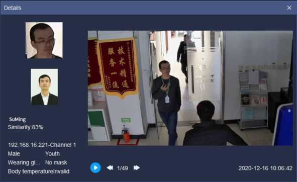
Figure 5.11.2
Click “Figure” and the retrieval result will be displayed in figure, the detailed information of captured picture and playback information will be checked, as shown in below figure:
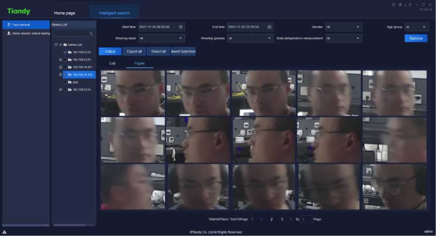
![]()
Figure 5.11.3
Select any data in the retrieval result and click
” to download this
data result to local device, the exported result is shown as in below figure:
| Snapshot 2020-11-2 | Channel rGender
192.168. liale |
Age groupWearing | gWearing jt | Body tempBig pictLSmall picture path
0 E: /T e s t / e E: /T e s t / e a s y 7 /F a c eP i < |
:/20 | ||
| Youth | Wearing | gNo | mask | ||||
| 2020-11-3 | 192. 168. IFemale | Youth | Wearing | gNo | mask | 0 E:/Test/eE:/Test/e as y7/Fa c eP i< | :/20 |
| 2020-11-3 | 192.168. liale | Junior | Wearing | g Wearing jt | 0 E: /T e s t / e E: /T e s t / e a s y7 /F a c eP i < | :/20 | |
| 2020-11-3 | 192.168. liale | Youth | Wearing | gNo | mask | 0 E: /T e s t / e E: /T e s t / e a s y7 /F a c eP i < | :/20 |
| 2020-11-3 | 192.168. liale | Youth | Not weariNo | mask | 0 E: /T e s t / e E: /T e s t / e a s y7 /F a c eP i < | :/20 | |
| 2020-11-3 | 192.168. liale | Youth | Wearing | gNo | mask | 0 E: /T e s t / e E: /T e s t / e a s y7 /F a c eP i < | :/20 |
| 2020-11-3 | 192.168. liale | Youth | Not weariNo | mask | 0 E: /T e s t / e E: /T e s t / e a s y7 /F a c eP i < | :/20 | |
| 2020-11-2 | 192.168. liale | Youth | Wearing | gNo | mask | 0 E: /T e s t / e E: /T e s t / e a s y7 /F a c eP i < | :/20 |
| 2020-11-3 | 192.168. liale | Youth | Wearing | gNo | mask | 0 E: /T e s t / e E: /T e s t / e a s y7 /F a c eP i < | :/20 |
| 2020-11-3 | 192.168. liale | Youth | Wearing | gNo | mask | 0 E: /T e s t / e E: /T e s t / e a s y7 /F a c eP i < | :/20 |
| 2020-11-3 | 192.168. liale | Youth | Wearing | gNo | mask | 0 E: /T e s t / e E: /T e s t / e a s y7 /F a c eP i < | :/20 |
| 2020-11-3 | 192.168. liale | Youth | Wearing | gNo | mask | 0 E: /T e s t / e E: /T e s t / e a s y7 /F a c eP i < | :/20 |
| 2020-11-3 | 192.168. Hale | Middle | agNot weariNo | mask | 0 E:/Test/e E:/Test/eas y7/Fa c eP i < | :/20 | |
| 2020-11-3 | 192.168. liale | Youth | Not weariWearing n | 0 E: /T e s t / e E: /T e s t / e a s y7 /F a c eP i < | :/20 | ||
| 2020-11-2 | 192.168. liale | Youth | Not weariWearing n | 0 E: /T e s t / e E: /T e s t / e a s y7 /F a c eP i < | :/20 | ||
Figure 5.11.4
Click
” Exoc t c
to export all retrieved results.
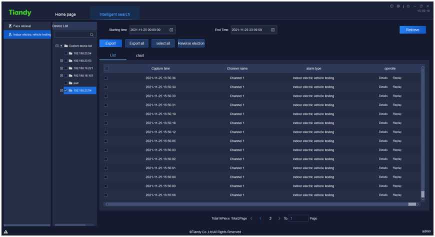
Figure5.11.2.1
Search can be based on beginning and ending time.
Users can choose equipment that supports the algorithm from left
monitoring points, set query conditions and click
Retrieve
” to find all recorded
detailed information of the monitoring point during the time. The information can
![]() be presented in list format or graph format.
be presented in list format or graph format.
Search result can be presented in list format by clicking
including capture time, channel name, alarm type etc. The detailed information
of captured image can be seen by clicking “
Details
” as shown below. Click
Replay
” to watch playback.
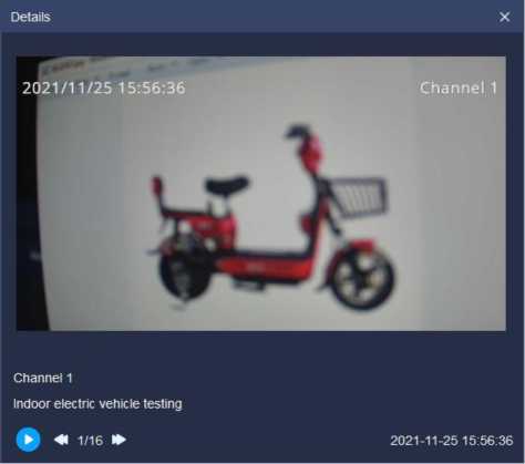 Search result can be presented in graph format by clicking
Figure5.11.2.2
![]()
![]() Detailed information of captured image and playback information can be seen as shown below.
Detailed information of captured image and playback information can be seen as shown below.
Choose any datum from search result and click “
” to download the
data; or click
Export all
” to export all search results.
| Details | X | |
| 2021/11/25 15:56:33 | Channel 1 | |
| B | ||
| Channel 1 | ||
| Indoor electric vehicle testing | ||
| ► ◄< 1/15 !► | 2021-11-2515:56:34 |
Figure5.11.2.3

Click the data statistics icon
on home page to enter the data statistics
interface.
Face statistics supports to carry out statistics by age group, by gender, by the number of people, by whether wear glasses, by whether wear mask and by body temperature measurement.
According to age group, the face statistics can be divided into junior, youth, middle age and old age to display. The platform supports list and graphic
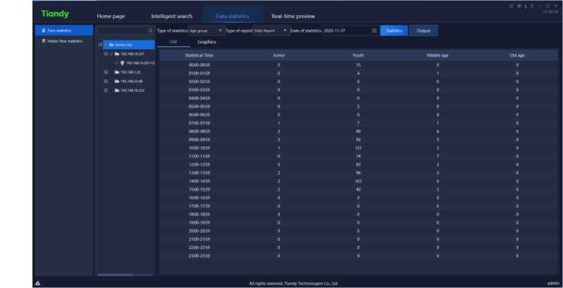
display, as shown in below figure.
Figure 5.12.1.1
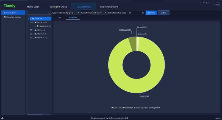
Figure 5.12.1.2
According to gender, the face statistics can be divided into male, female and unknown to display. The platform supports list and graphic display, as shown in below figure.
[Note] :When the device detects people shape but does not detect face, it will display “unknown”.
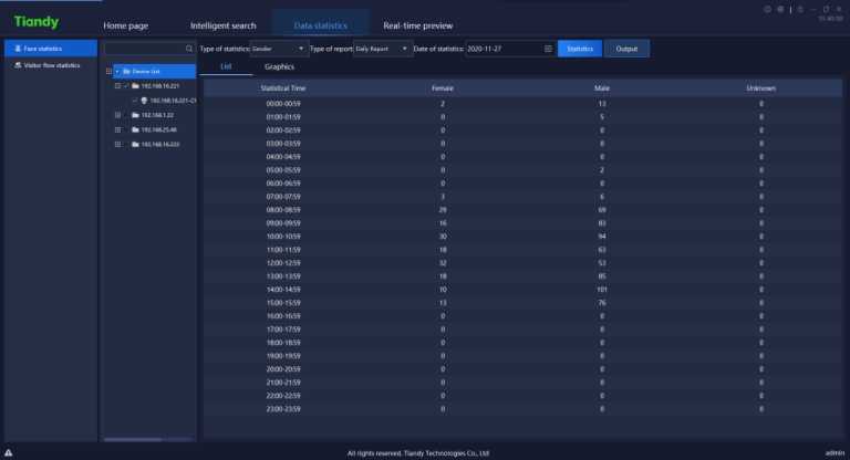
Figure 5.12.1.3
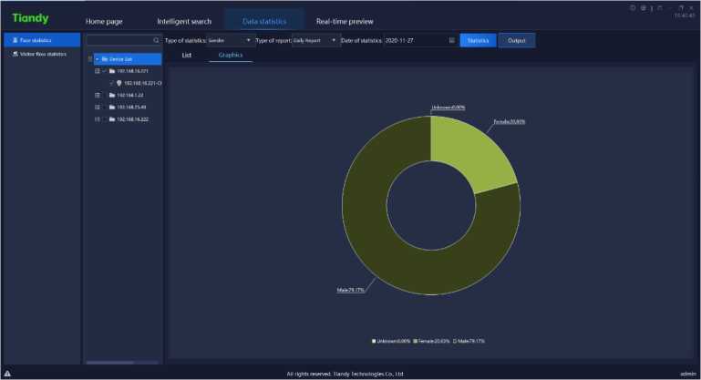
Figure 5.12.1.4
The statistics of the number of people every hour in face statistics. The
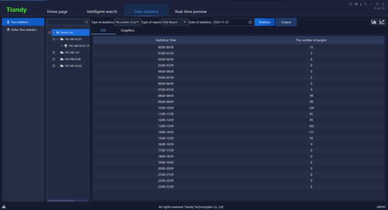


platform supports list and graphic display, as shown in below figure.
Figure 5.12.1.5
In graphic interface, click
to switch to line chart display, click
” to switch to bar graph display.
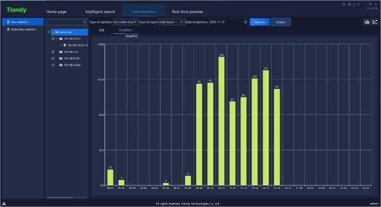
Figure 5.12.1.6
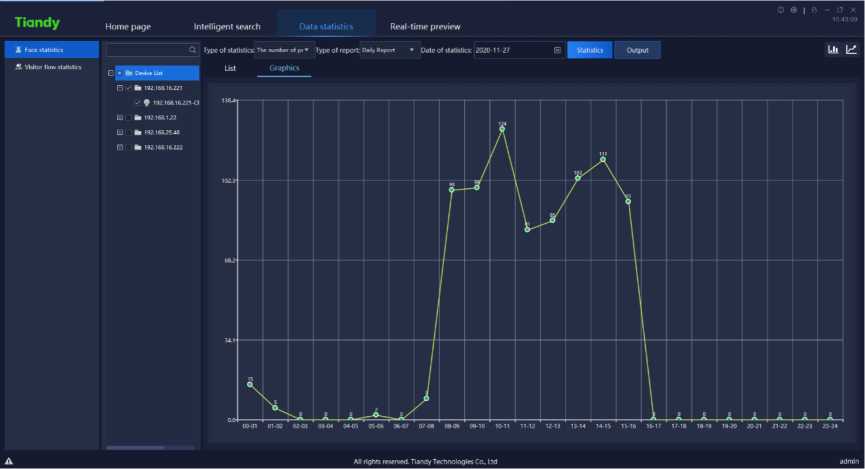
Figure 5.12.1.7
The statistics of whether wearing glasses in face statistics, can be divided into not wearing glasses and wearing glasses to display. The platform supports list and graphic display, as shown in below figure.
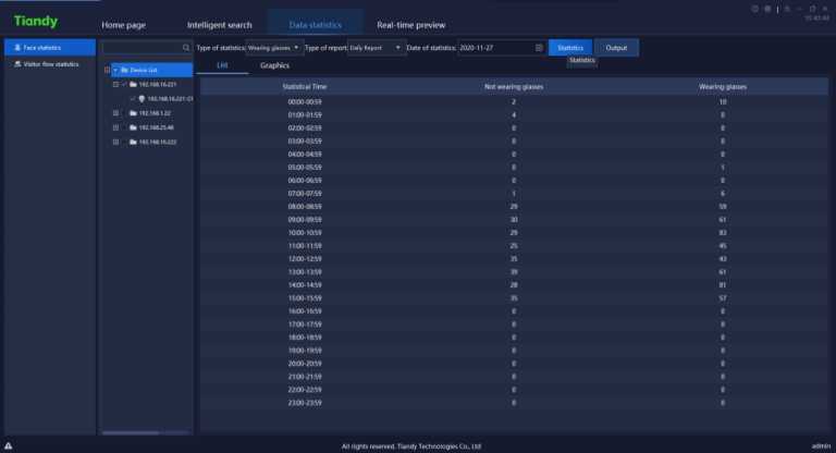
Figure 5.12.1.8
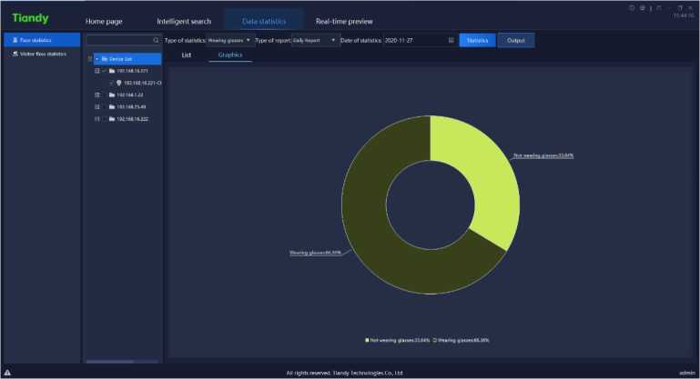
Figure 5.12.1.9
The statistics of whether wearing mask in face statistics, can be divided into no mask and wearing mask to display. The platform supports list and graphic display, as shown in below figure.
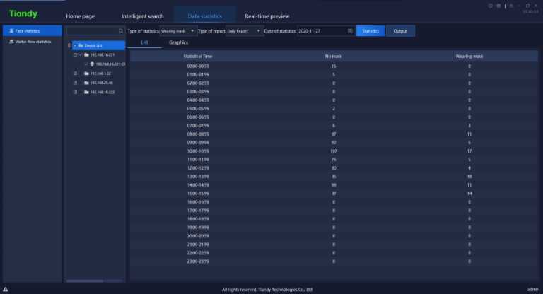
Figure 5.12.1.10
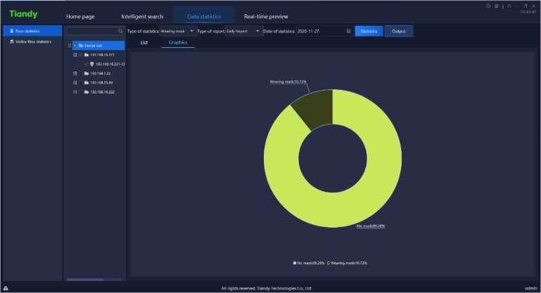
Figure 5.12.1.11
The face statistics will conduct statistics of the number of people with abnormal body temperature every hour by time. The platform supports list and graphic display, as shown in below figure.
![]()

![]()
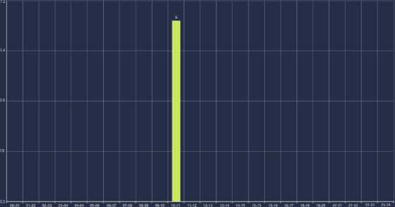
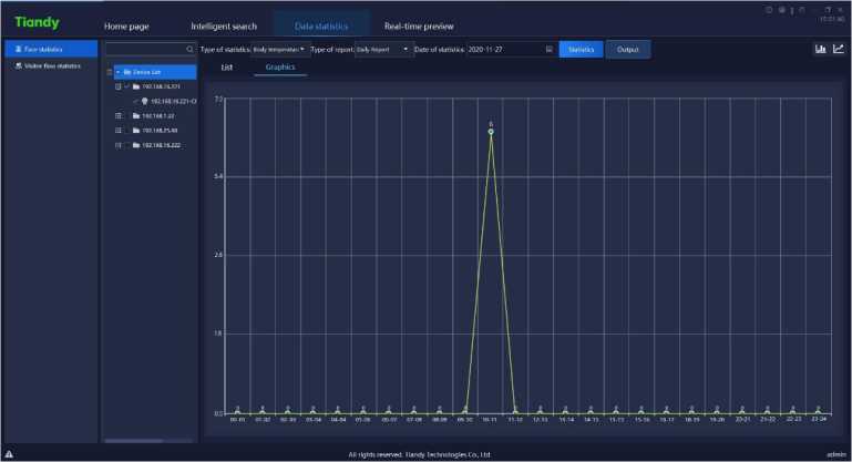
Tiandy
Intelligent search
Home page
Real-time preview
All rights reservea. lianoy technologies co. Ltd
Figure 5.12.1.12
| Tiandy | Home page | Intelligent search | Data statistics Real-time preview | IS SI-21 | |||
| ■ | Ldi | ||||||
| vr lypcoi wailSTICS rooy icr-tccrecur. • 1 ypc CT topun. ‘ncpon • vale CT statistics: af£V 1 di | Statistics | Output | |||||
| — | |||||||
| H Visitor flow ctaTotrc | * ■■ Device list | Lisi | Graphics | ||||
| □ -r fc 192.168.16221 | Statistical Time
00000059 01P0-0159 0200 0259 |
||||||
| ✓ ♦ i9ai«a.r«22io
□ 192.roa.1J2 0 I b l92.lfia.25AS |
0 0 | ||||||
| Fl k 192168.16222 | !İîİSİİi!8!îSݧİİiİSS | 0 0
0 0 0 0 0 6 0 0 0 0 0 0 0 0 0 0 0 0 0 |
|||||
| A | All rights reserved. Handy technologies Co, ltd | admin | |||||
Figure 5.12.1.13
Guest flow statistics supports two methods namely real-time statistics and report statistics. Real-time statistics can monitor the real-time guest flow according to the established area, and give an alarm when the number of person hikes too much; the report statistics can count the number of people entering, leaving and passing by in the established area, and display them with a list or a graph, as is shown in below figure:
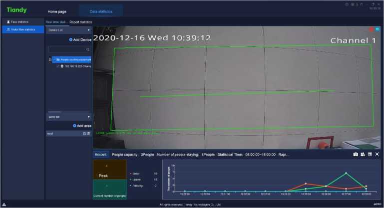
Figure5.12.2.1
Enter the device list bar, type in the key information in the search box, and double-click to locate the guest flow equipment, as is shown in below figure:
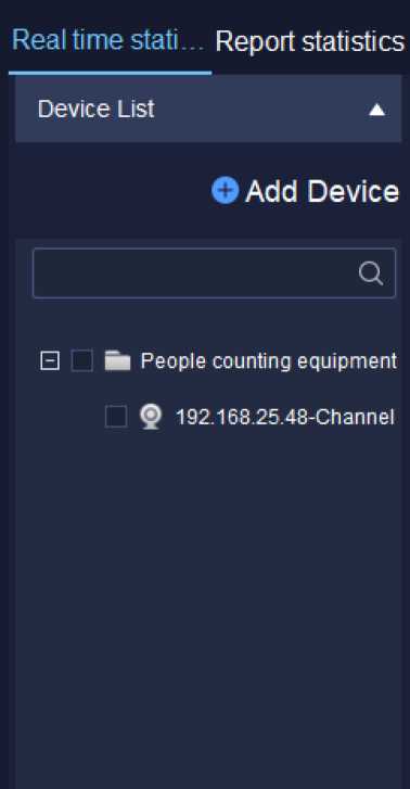
Figure5.12.2.2
Select the device in the guest flow device list and right-click to pop up the right-click menu of guest flow device list, as is shown in below figure:
Analysis configuration
Login to the affiliated host computer
Log off the affiliated host computer
Turn off all videos
Main code stream
Subcode stream
Video interruption
Time calibration
Manual alarm
Figure5.12.2.3
Select “ Analyse Config.” to enter configuration tool page to view the
configuration of each present channel, as is shown in below figure:
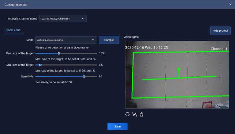
Figure 5.12.2.4
Relative parameters explanation of the interface is as below:
| Parameters | Explanation |
| Analysis channel name | Switch channels and analyse the configuration of each channel. |
| Mode | Read the algorithm supported by the front-end device and draw it in the right video frame or directly in the video frame. |
| Sample | Display the effect sketch shown in the video box. |
| Max. Size of the target | Display the maximum size of the target, and the range can be set from 6% to 30% |
| Min. Size of the | Display the minimum size of the target, and the range can |
| target | be set from 5% to 20% |
| Sensitivity | Set the detection sensitivity. The higher the sensitivity, the more sensitive it is. The range can be set from 0 to 100. |
| Video frame | Display the video and its algorithm under the channel. |
| Hide prompt | Hide the prompts in the configuration information on the left. |
| o | Redraw the statistical area in the video graph. |
| Redraw the statistical lines in the video graph. | |
| Eliminate the lines. |
Table 5.12.2.1
Other right-click menu button 5.2.1 device listo
Click
©Add Device
in device list to enter guest flow camera configuration
page, as is shown in below figure:
Figure 5.12.2.5
| Parameters | Explanation |
| In the left device list, select the device or device channel.
In the right guest flow camera list, select a group, and click to add the device or device channel to the guest flow camera group. In the right guest flow camera list, select a group or device channel, and click to delete the group and its device channel or device channel from the guest flow camera list. |
Relative parameters explanation of the interface is as below:
t/ Export
t/ Export
+ Add Group
In the right guest flow camera list, select the node and click to add the guest flow group.
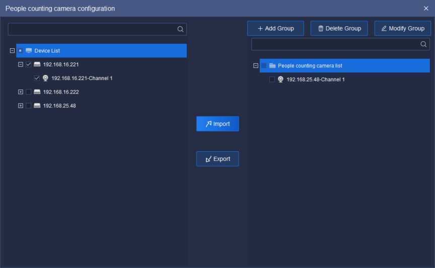

In the right guest flow camera list, select a group and click to delete the guest flow group.
O Delete Group
In the right guest flow camera list, select the node and click to modify the guest flow group name.
0 Modify Group
Table 5.12.2.2
Enter the area list to shift area scene, as is shown in below figure:
Zone list
Old school
Figure5.12.2.6
In the area list, click “i to delete established area, click “Ej” to update the
configuration information of present area
, click “
©Add area
to enter the area
configuration page to set information of area detection time, capacity, number of people surge, whether or not to enable alarm, detection device channel, etc, as is shown in below figure:
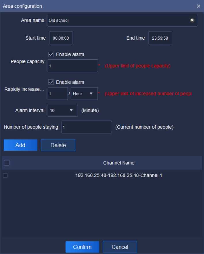
Figure 5.12.2.7
Relative parameters explanation of the interface is as below:
| Parameters | Explanation |
| Area name | Set the name of the detection area to facilitate the rapid positioning of the area. |
| Start time/End time | Set the time of starting and finishing of statistics. |
| People capacity | Set the upper limit of the capacity. This is required. |
| Set the upper limit of the increase of the number of people | |
| Rapidly increased | in the unit time (10 minutes, 30 minutes, 1 hour, 2 hours). |
| number of people | This is a required field.
Set alarm interval, supporting 10, 20, 30, 40, 50, 60 |
| Alarm interval | minutes. |
| Number of people | Set the current number of existing people. |
| staying | Set the detected channel video to be detected. Multiple channel videos adding is possible.
Select the channel video to be deleted. Multiple channel videos deletion is possible. |
Table 5.12.2.3
Add
Add
Delete
Delete
5.12.2.3. Real-time Data of Real-time Statistics
Select the area to be viewed in the area list, and the configuration information of the area can be viewed at the bottom of the interface, as is shown
in below figure:
Figure 5.12.2.8
Relative parameters explanation of the interface is as below:

| Parameters | Explanation |
| Recount | Click to eliminate the recorded number of people. |
| Peak | Record the maximum number of people in current area. |
| Current number of people | Record the number of people at current time. If the number exceeds the one that can be accommodated, it will turn into a red box; otherwise, it will be a green box. |
| Enter/Leave/Passing | Record the number of people in three status namely entering / leaving / passing by. At the same time, the color of each case is distinguished. Red colour represents entering, green leaving, and blue passing by. |
| Real-time Line Chart | The number of people is displayed in real time according to minutes. Red represents entering, green represents leaving, and blue represents passing. |
| B | Capture, capture picture save path can be changed from [system settings] > [common settings] > [path settings]. |
| K | Start all videos. The video download and save path can be changed from system Settings > Common Settings > Path Settings. |
| ini | Set the number of pictures, supporting picture display amount 1,4, 9, 36, 49, 64. |
| l”j | Full screen, full screen display of video page and realtime data page. Click again to cancel the full screen. |
Table 5.12.2.4
5.12.2.4. Video Page of Real-time Statistics
View the video effect of real-time preview in video page, as is shown in below figure:
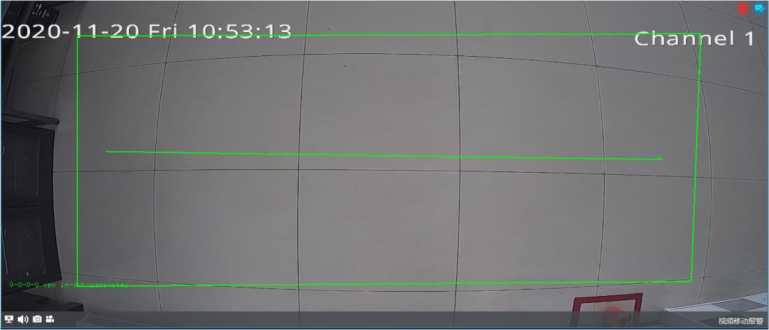
Figure 5.12.2.9
Refer to 5.2.2 Video Preview Window for page-related parameters. :
5.12.2.5. Report statistics
On the report statistics page, count the number of people in a selected area. It supports the statistics of the number of people entering, leaving and passing by according to the detailed time, as is shown in below figure:
Tiandy
Home page
System configuration
Real-time preview
Date statistics
Eouipment management
Face statistics
Type or report. Oaih Recon Statistics Output E) < * Ota school B * Outcbor List Graphics
staosiKai me
00 004»»
01 004)1 »
02 004)2»
03 004»»
04:00-04»
05 004»»
06 00 06»
07 00-07»
06:00-08»
09:004»:»
10:00-10»
11:00-11:59
12:00-12»
13:00-13:»
14:00-14:»
15:00-15:»
Number or people entering
M nghts reserved Tiandy Technologies Co. Ltd
Figure 5.12.2.10
Select the report type and statistical time. If statistics need to be made according to the detailed time, enable the “detailed time” check box, and the statistics of the number of people in the detailed period will be displayed during the statistics. Click “export” to export the statistical data to the machine, as is
shown in below figure.
Tiandy
Home page
System configuration
Real-time preview
Data statistics
Equipment management
X Face statistics Real time stati Report statistics
•?. Visitor flow statistics Q
Type or report Daily Repon
□ • * Zoneliol
Statistics Output
□ m Old school
E m Outdoor List Graphics
▼ Date al stall 2020-11 -23
3 E7| Detail lime 09 ▼ 00 »
Number ot people leaving
Number ol people passing
0
All rights reserved Tiandy Ternnotogies Co, Lid
Figure 5.12.2.11
The data can be displayed in the two forms namely list or graph. The
graphic form supports line chart and bar chart, as shown in below figure:
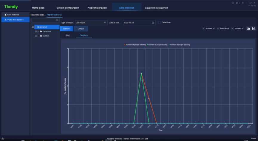
Figure 5.12.2.12
I lunay Homepage System configuration Real-time preview Data statistics tquipmerfl management
I Face statistics Real time stati Report statistics
•5 Visitor flow statistics Q
Type ol report Dmlv Report • Dateotslati 2020-11-23 H Detailtime
LJ ■ k Zonilist Statistics Output
S -r k Oto school ‘
□ k outdoor List Graphics
v Humber of s Number or Number or l.li \S Histogram
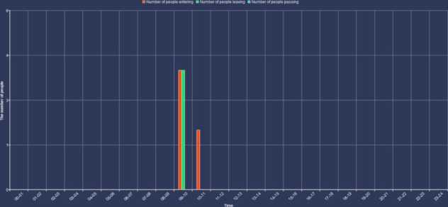
Figure 5.12.2.13

Click the alarm configuration icon on home page to enter the alarm
configuration interface. To conduct alarm configuration on watch point and device respectively is supported.
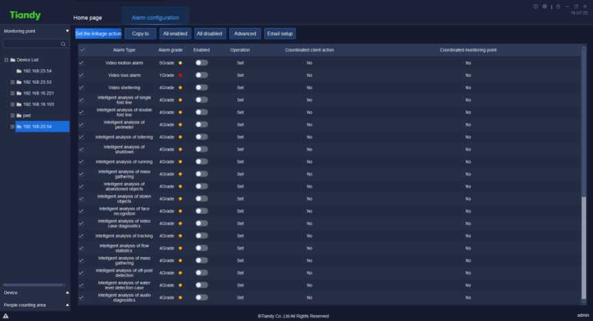
Figure 5.13.1.1
![]() Select the channel needs alarm configuration in the watch point on the left,
Select the channel needs alarm configuration in the watch point on the left,
, click “set”
tick and select required alarm type, set whether to enable
o|set coordinated action
to set the operation of coordinated alarm or coordinated
recording in corresponding alarm type, as shown in below figure:
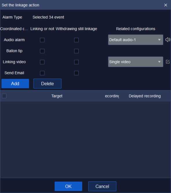
Figure 5.13.1.2
Note: Set linkage under defense deployment status by ticking “link or not”.
Linkage will take effect under defense withdrawal status by ticking “link or not” and “defense withdrawal enabled” at the same time.
Tick and select the check box ahead of “Audible alarm”, select alarm audio effect in the drop-down list, customized alarm audio supported (supported audio format is .wav), alarm audio audition supported.
Click Add and set “Coordinated monitoring point”, as shown in below figure:
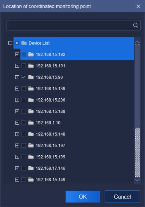
![]()
Figure 5.13.1.3
Select the channel needs to set recording, click
to add the
target channel of coordinated recording, click
Cancel
to restore to last
parameter setting. Click the number below or
Advanced
to continue to set
“Pre-recording” and “Delayed recording” time, as shown in below figure:
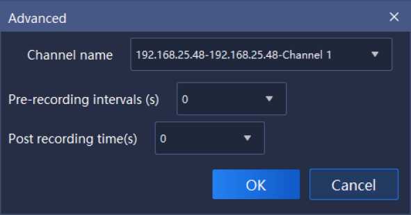
Figure 5.13.1.4
Pre-recording and delayed recording interval supports the time setting of
0s, 5s, 10s, 15s, 25s and 30s, click
OK
to save time setting, click ”
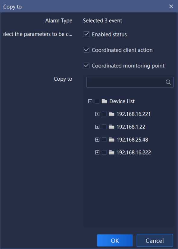
Cancel
Figure 5.13.1.5
to restore to last parameter setting.
![]() Click and select the type of alarm, click
Click and select the type of alarm, click
to copy the parameter of
Enabled status, Coordinated client action and Coordinated monitoring point of
the selected copy to other channel, as shown in below figure:
Click ”
channel.
All enabled
or
«disabled
to enable/disable all types of alarm in
the
5.13.1.5. Email setup
Click
Email setup
“button, and the E-mail can be configured. After
the
configuration is successful, the email alarm can be linked. As shown in the
figure below:
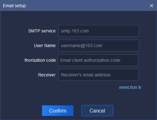
Figure5.13.1.6
Relative parameters explanation of the interface is as below:
| Parameters | Explanation |
| SMTP service | Configure the E-mail server address. |
| User name | Configure sender E-mail name. |
| Thorization code | Configure sender E-mail authorization code. |
| Receiver | Configure the recipient E-mail address. |
| Connection testing | Verify that this method can connect successfully. |
Table 5.13.1
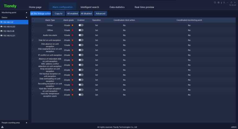
Figure 5.13.2.1
The specific operation is the same as the alarm configuration of monitoring point.
![]()
Tiandy
Home page
Data statistics
Equipment management
Alarm configuration
Monitoring point
Device
People counting area
•i westdoor
| Alarm Type | Alarm grade | Enabled | Operation | Coordinated client action | Coordinated mot |
|---|---|---|---|---|---|
| Capacity eweeded | iGrade • | Set | NO | No | |
| Alarm for surge | IGrade • | • | Set | No | No |
Set the linkage action Copy to All enabled All disabled Advanced
All rights reserved. Tiandy Technologies Co., Ltd
Figure 5.13.3.1
The specific operation is the same as the alarm configuration of monitoring point.
on home page to enter the operation
Click the operation log icon I
log interface. Login log, operation log and configuration log query supported, as
shown in below figure:
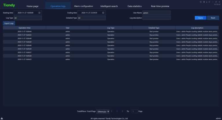
Figure 5.14
The description of related parameter in the interface is as follows:
| Parameter | Description |
| Starting time | Available to set the starting time of log query. |
| Ending time | Available to set the ending time of log query. |
| User name | Available to query the operation record of one user. Admin-super administrator user may check the operation record of all users. |
| Log Type | Available to query logs by type, including all, login, operation and configuration. |
| Detail Type | Available to conduct detailed classified query of all, login, operation and configuration by type. |
| Log description | Search key word to query log information. |
| Export Logs | Click Export Logs, available to output and save logs. |
| Query | Click Query, available to query logs according to query conditions. |
| Reset | Click Reset, to restore query conditions to default status. |
| Total X Pages | Display how many pages does the query result has. |
| To X Page | Select a page to jump to the log record on that page. |
Table 5.14
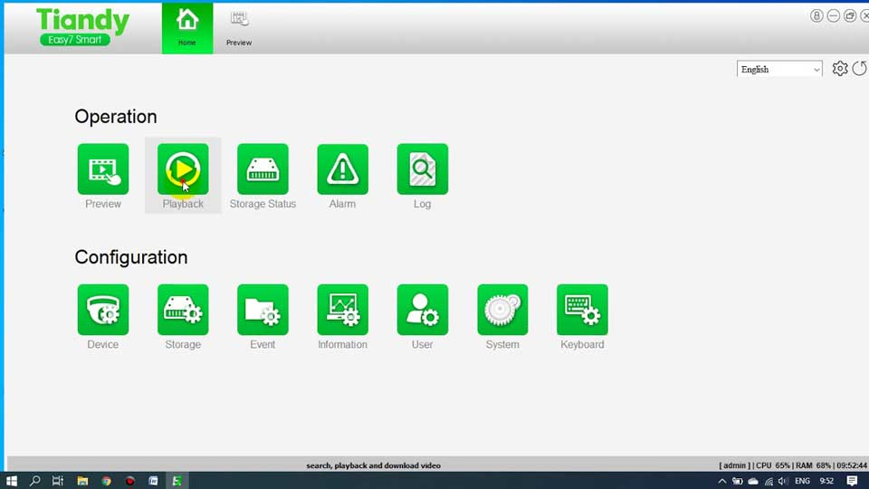


Isn’t it just thrilling to figure out how to tackle connection mishaps caused by playful pets? And decoding those mysterious system errors? Now, that’s what I call a tech rollercoaster!